Your ( very smart/clever) analysis does make perfect sense and seems confirmed by wavelength/dimension relation.
Hats off to you. And thank you sharing all this!
Hats off to you. And thank you sharing all this!
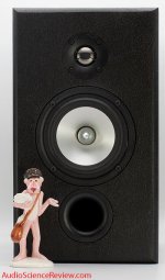
To me, it's interesting that the Zaph ZA5.2 has similar polars to the Revel, even though the Zaph has no waveguide.
When I looked closely at the Zaph polars, I see that the response from zero to forty degrees off axis are "bunched up" together.
This make me wonder if perhaps the waveguide-like effect of the cabinet shape is due to diffraction off the edges?
IE, radiation from the tweeter will interact with the cabinet edge. When that happens, it may create secondary sources. I would expect these secondary sources to narrow the bandwidth of the loudspeaker.
This is similar to having a second set of drivers located on the edge of the cabinet, but radiating with a time delay (due to the time difference between tweeter and edge.)
The time difference is 10cm, which would be anticipated to produce a dip at 1700Hz. (1700hz is one half wavelength of 10cm.)
The depth and the impact of the diffraction would depend on the beamwidth of the tweeter and the shape of the cabinet edges.
Another consideration - which is very likely - is that John Krutke and Kevin Voecks designed the width of their baffles to complement the crossover network. For instance, the Zaph speaker appears to have a crossover at 2khz, and this would place the dip below the xover point of the tweeter.
Attachments
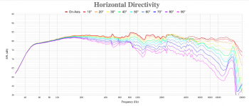

Here's the Revel and the Zaph side-by-side. Though the Zaph speaker definitely has a "waveguide like effect", the Revel is radiating about 3dB to the sidewalls even below the xover point. I'm guessing this is because the woofer and the tweeter are still interacting with each other in the octave below the xover point.
To me, it's interesting that the Zaph ZA5.2 has similar polars to the Revel, even though the Zaph has no waveguide.
...
Another consideration - which is very likely - is that John Krutke and Kevin Voecks designed the width of their baffles to complement the crossover network. For instance, the Zaph speaker appears to have a crossover at 2khz, and this would place the dip below the xover point of the tweeter.
The secondary point may also explain why the tweeter have no offset on lateral axis.
Now here is the question that arise from all this to me: are the designer aware of the 'waveguide effect' of the baffle or are the crossover point and dimension choosen for the face of loudspeaker just a coincidence or shape follow function of other parameters /compromise made (about the waveguide effect you mention being it from secondary emmission source or the curved face with waveguide) ?
For the LS50 it seems the designer are aware of it ( why bother with a more difficult build or more expensive cost in a commercial product which isn't a 'flagship' model?).
Maybe Earl Geddes could put a light on this as he may be aware of it too.
To be honest this is the first time ( from the different thread you made about it) i see this 'waveguide effect' from the box ever mentioned.
I wonder too if it have an effect on BSC too. ( what you mentioned about the Summa in this message https://www.diyaudio.com/forums/mul...es-lead-narrower-beamwidth-2.html#post5836692 made me think about it).
For the Zaph bsc should be located in the vicinity of 575hz and this could explain why the 0* to 40* are 'bunched together' as diffraction occurs all along til fc?
Overall the Revels seems 'better' or more naturally behaved directivity wise: less diffraction from the use of waveguide and more contoured shape?
I've not heard neither the Zaph or Revels but i would be curious about a comparison between them in particular if the Zaph have the 'pin point' imaging that i associate with design which doesn't put diffraction effect attenuation in the first priority on the design?
Anyway put a big roundover, a curved shaped face and a waveguide and you seems to have a winner combination about the box shape.
Last edited:
This IS baffle step.
But it's basically a more nuanced view of baffle step.
With most loudspeaker designs, we simply manipulate the on-axis frequency response to compensate for baffle step.
But it's more complex than that, because the transition from 2pi radiation to 4pi radiation is gradual, due to the dimensions of the loudspeaker enclosure, the impact of diffraction off of the edges, etc.
It's a tricky one, and the only practical way to simulate it, I think, is ABEC. And there are probably 10-20 guys in the world who are any good at ABEC. (I guess you could use Comsol too?)
Two dimensions simulations of this aren't great because the height of the enclosure will impact things too.
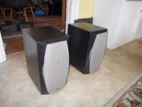
JBL, Revel, Infinity etc... they all use enclosures that are noticeably deep. Methinks this is probably for a reason: it's a way to push the frequency where the beamwidth widens down to a lower frequency, and it accomplishes this with a speaker that still has a WAF friendly narrow baffle.
Look at the Infinity IL10 for instance; that deep cabinet and those cutouts on the baffle can't be accidental.
But it's basically a more nuanced view of baffle step.
With most loudspeaker designs, we simply manipulate the on-axis frequency response to compensate for baffle step.
But it's more complex than that, because the transition from 2pi radiation to 4pi radiation is gradual, due to the dimensions of the loudspeaker enclosure, the impact of diffraction off of the edges, etc.
It's a tricky one, and the only practical way to simulate it, I think, is ABEC. And there are probably 10-20 guys in the world who are any good at ABEC. (I guess you could use Comsol too?)
Two dimensions simulations of this aren't great because the height of the enclosure will impact things too.
JBL, Revel, Infinity etc... they all use enclosures that are noticeably deep. Methinks this is probably for a reason: it's a way to push the frequency where the beamwidth widens down to a lower frequency, and it accomplishes this with a speaker that still has a WAF friendly narrow baffle.
Look at the Infinity IL10 for instance; that deep cabinet and those cutouts on the baffle can't be accidental.
Attachments
^ yes i think you are absolutely right about it.
I wondered too about the shift from the traditional 'large width baffle' to 'deep box with shaped front' in modern design.
I thought the 'pinpoint' was related to the freq range where the transition between 2pi to 4pi happened between the two approach but i've heard modern shaped box which wasn't as pinpoint as i would have expected them to be ( and despite too much attention pointed to diffraction but the particular model i think of was with horn/waveguide).
And yes the height play a role as can be seen from the recent works of the 'line array' guys in here ( Nc535, Wesayso,Fluid,...).
Thank you i think you made one of the piece of the puzzle i contemplate and which missed appear.
Patrick I can simulate a test box in ABEC for you if you want to quantify the effect. Make a drawing or specify the dimensions you want to look at. It is much easier to look at the drivers separately rather than together. And a woofer up to a few kHz can be simulated pretty quickly. A dome tweeter to 15K is much more time consuming.
Everything about the dimensions of a speaker play a part in it's overall directivity and you are right that to optimize a design everything needs to be considered.
Whether that was done with all designs, who knows but Harman and Genelec are using FEM/BEM simulation as part of the design process.
Don't discount that much is done for looks and has nothing to do with sound quality, sometimes the two coincide.
If you could throw together a model with a waveguide in a box that would go a long way to solving this mystery.
I can theoretically do it, but the last time I did a 3D model in ABEC it took the better part of my two week vacation. If you've figured out how to do it faster I'd love to know!
The thing that's time killing for me is translating the STL to a mesh
I can theoretically do it, but the last time I did a 3D model in ABEC it took the better part of my two week vacation. If you've figured out how to do it faster I'd love to know!
The thing that's time killing for me is translating the STL to a mesh
If you can give me some rough dimensions of the size of box that would be helpful to look at it won't be too hard.
I would not use an STL as a base it is much easier to use step files in gmsh.
For a rectangular cabinet the sides and back could be created from Nodes and then changing the size would just be a matter of changing the values in the solving script.
I just draw the outer surfaces in Fusion and split the model based on the symmetry that I can use to save CPU time.
Using a roundover or chamfer on the baffle edge helps to reduce diffraction and makes the simulation less noisy making it easier to see the directivity differences.
Adding a waveguide is slightly more complicated depending on the size. Using Ath to generate the waveguide and driver mesh is always better as it makes better use of the element sizes and stops it getting out of control.
That mesh can be exported from ABEC as an STL and used in Fusion to cut a hole in the baffle so the vertices align.
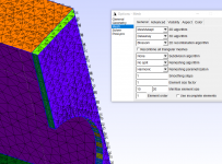
How do you go from Fusion to a mesh?
The software that I was using, (gmsh I think?) was forcing me to manually select every vertice, which was nightmarish
The software that I was using, (gmsh I think?) was forcing me to manually select every vertice, which was nightmarish
Revel M16 dimensions:
8-11/16"W x 14-7/8"H x 11"D
This would be a great starting point, basically stick a waveguide in the center of this box and see how ABEC simulates it. I don't really have much interest in how the woofer performs, it's the waveguide I'm curious about.
8-11/16"W x 14-7/8"H x 11"D
This would be a great starting point, basically stick a waveguide in the center of this box and see how ABEC simulates it. I don't really have much interest in how the woofer performs, it's the waveguide I'm curious about.
I'll have to get my calculator out to translate, I'll give it a try but I'll need to make a waveguide to suit or adapt one of augerpro's for this use.
I'm somewhat confused because if the tweeter is crossed out at 2K or above you won't see much effect from the directivity of it down at 500Hz.
There are so many factors that play into the end result that it is hard to generalize but we'll see if starting somewhere with this helps to make some things clearer.
22cm width x 28cm depth
You're right about the xover point, it might make more sense to sim a 17cm woofer instead.
You're right about the xover point, it might make more sense to sim a 17cm woofer instead.
How do you go from Fusion to a mesh?
The software that I was using, (gmsh I think?) was forcing me to manually select every vertice, which was nightmarish
Export from Fusion as a step (you probably exported as an stl which why gmsh tagged every triangle separately).
Open step file in gmesh, set the the mesh density, mesh in 2D and save. You can see the main surfaces all have the same tag.
Attachments
I have already run some simulations that krivium referred to I won't repost the images here but they are of a TC9 shaped cone in both a curved enclosure and a more regular one, and also the difference with putting a small chamfer between the driver and baffle. This shows the difference between the same driver in different enclosures. Links below showing the two main different configurations.
The making of: The Two Towers (a 25 driver Full Range line array)
The making of: The Two Towers (a 25 driver Full Range line array)
The making of: The Two Towers (a 25 driver Full Range line array)
The making of: The Two Towers (a 25 driver Full Range line array)
I created a cabinet model 230mm wide, 380 tall and 283mm deep and added a 13mm chamfer on the horizontal baffle edges. The woofer was something I already had modelled and is about 170mm diameter including the surround.
There are two variants one with a modelled woofer cone and the other with a flat disc radiator. The flat disc is more accurate above 1K and the cone more accurate below 1K due to how ABEC works. Neither have a lumped element script used as the point of this is to compare intrinsic directivity.


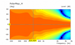
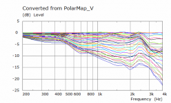
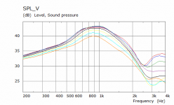
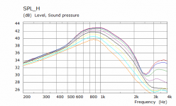
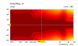
The virtual measurements are taken from the centre of the woofer cone and this shows a difference in the vertical due to the baffle height. Polars are normalized to the on axis 0 degrees.
Attached are the flat disc results
There are two variants one with a modelled woofer cone and the other with a flat disc radiator. The flat disc is more accurate above 1K and the cone more accurate below 1K due to how ABEC works. Neither have a lumped element script used as the point of this is to compare intrinsic directivity.
The virtual measurements are taken from the centre of the woofer cone and this shows a difference in the vertical due to the baffle height. Polars are normalized to the on axis 0 degrees.
Attached are the flat disc results
Attachments
-
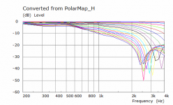 PB Cab Disc H Polar Curves.png13.3 KB · Views: 106
 -
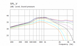 PB Cab Disc V SPL.png10.8 KB · Views: 102
 -
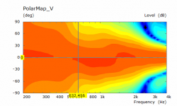 PB Cab Disc V Polar.png27.5 KB · Views: 109
 -
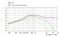 PB Cab Disc H SPL.png11.7 KB · Views: 107
 -
 PB Cab Disc H Polar.png25.9 KB · Views: 103
 -
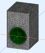 PB Test Cab Woofer Mesh.png210.2 KB · Views: 538
 -
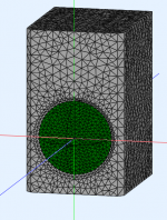 PB Test Cab Disc Mesh.png190 KB · Views: 610
Woofer cone results, you can see the dip that is introduced from the cone depth but cannot be relied on to be accurate. Below 1K this is more likely to be accurate than the other one.
Attachments

- Home
- Loudspeakers
- Multi-Way
- Curved Baffles Lead to Narrower Beamwidth