Thanks François
You're a great help, as usual! 🙂 That's what I was leaning toward too. I guess if I would have looked at your previous schematic, it would have become apparent what I needed to do.
So, what do you think of the cascode idea? Is it worth doing? Do you know if there is a reason not to use a zener to bias up the cascode transistor?
THanks again.
Steve
Thanks Steve, but I'm not worth the enthusiasm 🙂. I'm just trying to learn, as you do.
For cascode biasing, I really dont know which solution would be the best. I would manage some room on PCB in order to test either the resistor divider or the zener. The zener is obviously noisier than the resistor, but I'm not sure it will impact a lot on your listening tests.
The cascode operation is very appealing (at least for me), and I sure will give it a try in the future. My current (pun time...) BLS is almost the same than in my schematic, without the cascode, but with two cascAded stages (BLSwith gain -> Volume control -> BLS unity gain for buffering) But at such high currents/rail voltages, be prepared to need heavy heatsinking. I cannot resist to show you how far it can lead 😉
Happy soldering, and keep us informed of your progess
Attachments
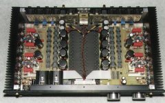
VERY NICE!
So, you have two stages cascaded with a volume control inserted between? Are those relays on the board for the volume control? So, how is the sound?
I can see how this project could keep expanding... Right now I'm considering building six channels in seperate enclosures with one central volume control using a pot to control relays in each chassis. I would use this for my 6 channel output on my SACD. It will probably start out as just a 2 channel, but with the ability to expand as much as needed.Thanks for the great picture.
Steve
Yes, 16 relays for volume control, 64 steps, 1.25 dB/step. Just 2 resitors in the signal path at a given level. Sound is more than great !
I added relays to switch bias current down to 15 mA when the beast is in stand-by, just to reduce warm-up time.
Good luck for your six channels ! May all your winters be warm 😀
Cheers
I added relays to switch bias current down to 15 mA when the beast is in stand-by, just to reduce warm-up time.
Good luck for your six channels ! May all your winters be warm 😀
Cheers
François,
Would you be willing to tell me how you set up your volume control? I'm still looking into that, and 16 relays to get 64 steps sounds better than any other way I've found.
Steve
Would you be willing to tell me how you set up your volume control? I'm still looking into that, and 16 relays to get 64 steps sounds better than any other way I've found.
Steve
Steve,
The volume control is in fact two cascaded attenuators. The idea's not mine (Thanks Yves 😉), but it's working damn good. The first eight relays provide 10dB steps (from 0 to -70dB), and they're followed by a 1.25dB/step attenuator. So the attenuation ranges from 0 to -78.25 dB. I use a quadrature encoder attached to a microcontroller, which uses 6 bits to drive relays trough 2 3->8 decoders. The 3 MSBs drive the 10dB steps, while the 3 LSBs are devoted to the 1.25dB.
With some additional glue logic and assembler code, you can make it work in a "make before break" mode.
I don't have the schematic handy, but I can mail it to you next monday, as soon as I get my hands on it.
Cheers
Well, due to the tremendous demand (how quick you are 😉), and if you promise me to be good boys 'till Monday, I'll post it.
The attenuators are straightforward, and can be calculated quite simply. You can make your own steps, provided that the larger step is 8 times higher than the small one.
I'll sure will be having difficulties to explain the MBB sequence in english... May you forgive me 🙁
The attenuators are straightforward, and can be calculated quite simply. You can make your own steps, provided that the larger step is 8 times higher than the small one.
I'll sure will be having difficulties to explain the MBB sequence in english... May you forgive me 🙁
Stepped Volume Control
"Chose promise, chose due" 😉
Well, due to file size limit, I had to post the schematics in a zipped PDF. You will find the volume control in two flavours. Common points are the top of page logic and 10dB steps first, followed by the 1.25dB steps.
The attenuators are almost classical, but you must pay attention to the fact that the two atts are cascaded. In this configuration, the first is loaded by the second, and it must be accounted for when calculating resistor values in the 1st attenuator. With schematics values, the equivalent pot value would be of about 5K.
The "make before break" is in fact quite simple. It's just a matter of latches (HC573). At a given time, the volume value decoded by the upper HC238 (unlatched) and the lower ones (latched) are the same. When volume changes, the new MSBs and LSBs are immediately decoded using the upper HC238s, while the lower ones keep memory of the previous volume. At this point, the new ("make") and old values both exist on the relays, through the discrete OR Gates(the diodes+47K resistors). Shortly after (about 5ms in my case, the time needed by the relays to swhitch on), a "Latch MBB" signal updates the output of the latched HC238s, thus only the new volume value is seen by the relays. And that's it 🙂
However, MBB must not be activated when the LSBs go from 111->000 (vol up) or 000->111 (vol down) : in these cases, the 10 dB steps are changed, and the "cohabitation" of two 10dB steps, added with the "111" LSBs leads to a short passage throug loud volume.( I'm not sure I'm clear here 😕 )
Well, any comments/flames appreciated 🙂
Cheers,
Attachments
François,
Thanks for the zipped schematic. I have looked it over, and it seems pretty straighforward.
So, you don't activate the latch when you change steps on the 10db scale? Does this lead to a small glitch in volume levels? (not that I'm concerned... )
This really helps me out A LOT! Thanks for posting it.
Steve
Steve,
This may lead to small glitches, but far smaller than if you latch every time. In fact, I'm not hearing'em at all.
If you latch every time, you will hear it ! And you'll hear it more if the volume is high.
Well, in fact, I've not explained it right. You latch ALL THE TIME (otherwise, it won't work 🙂 ), but when moving the 10dB steps, DON'T WAIT the famous 5ms for the relays to stabilize. In this case, the latch pulse must be sent immediately after the new volume value is sent.
It's not very easy to explain (bad english🙁 ), but I'll try :
Suppose you want to go from 100111 (MSB first) to 101000.
if you "decode" it "manually" :
100 -> 4th 10dB relay -> -40dB
111 -> 8th 1.25dB relay -> 0dB -> Total att:-40dB
want to switch to :
101 -> 5th 10dB -> -30dB
000 -> 1st 1.25dB-> -8.25 dB -> Total att: -38.25dB
Well, quite simple, uh ?
but during a short time, when both combinations exist, you will meet a weird situation, where, in the 1.25dB step att., the -8.25 dB will be bypassed by the 0dB. Thus, you will "quieltly" jump from -40dB to -30dB, and back to -38.25dB.
If you don't allow sufficient time here for the relay to switch in and out, the transition won't be heard. The time taken by the previous relays to switch off while the others sitch on almost compensate, and the transition will be much quieter.
In fact, this MBB is not mandatory, it just accounts for small differences between relays switching times (and it was just a way for me to play with a uC 🙂 ) But its price is not very high, and you can bypass it by software. I've tested with and without, and found that some of the relays were slower than the others, and it could be heard...
Hope this is clearer 😕
Cheers
Alright, I think I have it now. You aren't latching during the changes, you're UNlatching after your 5mS relay switch time is over, except when you're changing the 10db relays, when you want to unlatch immediately. correct?
Thanks again... this is a nice setup, IMO.
By the way, any suggestions on µC's? This will be my first project using them, and I was going to use an 8bit Atmel AVR since I have a developer's kit for it. I still haven't found a lot of information for interfacing the graycode encoder.
Steve
Thanks again... this is a nice setup, IMO.
By the way, any suggestions on µC's? This will be my first project using them, and I was going to use an 8bit Atmel AVR since I have a developer's kit for it. I still haven't found a lot of information for interfacing the graycode encoder.
Steve
1) Correct, got it !
But forget "(UN)latch". It's easier for me, since my vocabulary is quite limited, but I'd rather say "put in memory". I give the new volume value, wait 5 mS (depends on your relay type), and memorize this new value....Except when there's a 10dB change, where the sequence is the same, except that I don't wait at all (just 1 uC clock cycle).
2) I used an AVR. Quite easy to program, and the ISP is a must to test various features. The gray decoding is relatively simple. I use a lookup table in eeprom, addressed by the nibble made of the 2 bits previous value and the 2 bits new value to know if I must go up or down or do nothing.
Hey, sounds good! Thanks for the help. Have you ever thought of using fets instead of relays?
Steve
Steve
Well, the relays noise is quite bearable, and I'm not sure Fets will withstand +/-30V p-p 😉 But who knows, maybe in a future life...
Cheers
Cheers
C8, C6, C8, C9 should be before R18, R19 not after them. The low impedance they present to the gate of the MOSFETs at high frequencies may cause oscillation as mention by Nelson on his site.
Why two biasing networks?
Perhaps I've missed the point, but I think you can eliminate one of your biasing networks. In the second schematic posted by SteveG, there is a biasing network with three resistors and two capacitors for each side of the circuit, but the idea is simply to put 8.33V at the gate of each of the FETs. So why not use the same biasing network for each side? That is, tie the gates on Q3 and Q4 together.
I'm also baffled why you want to use so many pots. I can see using one in a unified bias network for Q3 and Q4, but the pot for R20 and R21 seems gratuitous.
I guess I would also lose the current sensing resistors. Where do you get 1Ohm current sensors? I don't know either. The best you would get there is 1% tolerance anyway. If it makes you nervous use something accurate for the current source resistor.
In case nobody can tell, I'm designing my BoSoZ right now. 🙂
- Status
- Not open for further replies.
- Home
- Amplifiers
- Pass Labs
- current sourced cascoded BLS schematic