And some additions to my lab, which is now capable of every electrical measurement known to men, from 1uHz to 40GHz, and down to -140dB distortion and noise (the microscope is showing my age 🙂) But somehow I don't believe a 40GHz wideband audio amplifier would win the Absolute Sound prize, though.
The rest are details 😛.
That picture gives a whole new meaning to 'The wall of sound'!

Jan
I am looking for a clear and simple definition of CFA. I may have missed it, if one has been proposed, could you give it ?We’ve defined on numerous occasions current output and current feedback within the canonical amplifier topologies.
In the most simple form of CFA's and VFA's, the input transistor receives on its emitter the feedback voltage, buffered in a VFA, not buffered in a CFA. The insertion of the buffer is not without consequence but the fundamental mechanism is the same, have I to recall it ?There is no confusion about what they are and how they operate. If you are confused or cannot accept this, it is up to you to make the effort close your knowledge gap, or remedy your misunderstandings.
There is no confusion in my mind as to why VFA’s and CFA’s are different and operate on fundamentally different mechanisms at the topological level.
Ask youself :Trying to reason with you on these matters, with all due respect forr, seems pointless.
- why your arguments are not convincing Forr.
- why Forr is told to be wrong while his arguments are not discussed to prove they are wrong.
By the way, I modified my post #1 to give links to texts of various texts about CFA (without favouring a point of view, I hope).
Wow - some good stuff in there. You and RJM must run pretty close for range of equipment.
I know SY has an AP - I saw it on YouTube.
Are you still using your Pretty Good Amplifier?
I hate APs with a passion. For the bottom of distortions level measurements, I have a Rohde UPD with Option B1 (low distortion analog generator) and two (long story why) Panasonic 7722A analyzers.
Yes, in one of my systems. But I have a much more powerful one (different circuit) in my main system, 400W/8ohm 800W/4ohm feeding a pair of (otherwise very difficult to drive) Infinity Kappa 100 giants. The PGP is feeding a pair of B&W 802 Series 80, outstanding sweet sound.
Last edited:
Ask youself :
- why your arguments are not convincing Forr.
- why Forr is told to be wrong while his arguments are not discussed to prove they are wrong.
I cannot answer your question, since I did not follow the whole discussion, but I would add my own question:
How come I (and I suppose many other, even some of the John Curl circuit topologies are essentially CFAs) successfully survived designing discrete "CFAs" and benefiting from their circuit topology properties, before some smart panty IC engineer (David Nelson at Comlinear in 1982?) came up with the actual "CFA" IC concept?
If I remember correctly, 40 years ago (sounds familiar?) discrete "CFAs" were, in various incarnations, textbook examples of circuits with maximum GBW (small signal) and high slew rates. Nobody called them CFA then, they were just another implementation of a shunt output, serial input feedback topology, with their advantages and limitations.
"Ask youself :
- why your arguments are not convincing Forr.
- why Forr is told to be wrong while his arguments are not discussed to prove they are wrong."
Come on forr! I know its Christmas but you cannot seriously think we are going to fall for that one!
Everyone has tried to point out in as nice a way as possible the error in your thinking and point you in the direction.
If forr is not convinced, then the problem lies with forr and not with electrical science and engineering - lets be clear and honest about that at least.
Forr, It seems CFA operation has been discussed here in all and every détails and that you are stuck by a simple semantic obstacle.I am looking for a clear and simple definition of CFA. I may have missed it, if one has been proposed, could you give it ?
In French, some brand names are used to define objects, like "Frigidaire" ou "mobylette". Who cares, as long as everybody know what object is designed by those "sounds"/"letters" ?
So, why don't you forget this voltage and current names? Currents and voltages are two ways to look at the same physical phenomena: the way electrons flow in a circuit. That is resumed in a very simple formula: V=ZI.
I will not make you insult to remind you how a transistor works, nor how we analyze the poles in a closed loop.
All the answers on the differences between these two topologies are summarized comparing what happens in a "long tailed pair" and in a simple transistor, mounted in common emitter, on which one makes vary *current* between emitter and base (and their consequences on the current that flows in the collector) applying a tension to the emitter (as you like to think ;-).
It is a very old and smart idea, to use the same tube working in common cathode for the +input and in common anode for the inverting one.
As I see things, the major advantage of this topology is to can have, in the same time, a high impedance in the +input (good for the preamp) and a low impedance in the feedback loop that can null the pole produced by the feedback impedance and the parasitic capacitance in the emitter. Pole that is inside the feedback loop.
The reason why common base is often preferred for HF operations.
Hoping that my poor English will all make-you laugh ;-)
Last edited:
Ok, let's narrow the definitions and be careful how to name things.
I won't make use of the name Middlebrook anymore, he used it for the General Feedback Theorem or GFT, for which I found this very interesting PDF.
https://web.archive.org/web/20160331135833/http://ardem.com/downloads/GFTManual.pdf
Thanks for the reference.
But contrary to your belief, to my opinion he used the voltage and current injection technique right before the input and not just anywhere in the circuit.
That's the obvious point of interest, and I won't dispute that that's the point that he probably thought would be most useful. But the theory does apply to all points within a loop. It is clear that T is constant everywhere within a given circuit, but Ti and Tv will vary depending on which point is selected.
Agreed, nice choice of term. Prefer DFM to avoid confusion.I will use the name "DIT" to identify the Dominant feedback mechanism" or DFM for short and not use it to prove whether you have to do with a CFA or a VFA.
But it certainly can be used as a useful first indicator.
Look at your own construction in the image below with a current source in the feedback loop.
I see no use at all for such a construction, but under strict conditions it came out as having current as DFM.
However cutting the loop at the other end made the DFM look as voltage. But both cases are telling nothing about the topology.
Same situation you created with a VFA where a a low ohmic resistor R was inserted in front of the negative input, staying right there after the loop was opened for DIT.
The DIT will now tell the DFM to be current. Again rather pointless.
When the cut was made for inserting DIT between the junction of R-Rf and the negative input instead, DIT would have identified this circuit as having voltage as the DFM.
It is hardly pointless. These circuits exist and can be built and measured (at least the 100 ohm one - I built and measured it and published the results.) Most importantly, they demonstrate that with an arbitrarily chosen feedback network, DIT cannot be trusted to identify whether the gain block topology is CFA or VFA. The fact that these circuits aren't useful is irrelevant. Since the possibility of the existence of a similarly behaving circuit that is useful cannot be ruled out, the point made here is a very practical one, speaking directly to Question #3 below.
So with this, I think I can answer your questions at the end:
Does a test exist which can demonstrate the predominant form of feedback at any point within a closed loop circuit? I think we can both say yes
I think with the two examples above I have to say no. The outcome differs completely depending on where you make the cut.
Our communication problems intervene again. Please consider the phrases in bold (you already used italics; I don't mean to be so emphatic.) From my reading we are saying the same thing. Let me rephrase: Given any point within a given circuit, the application of DIT will determine the DFM at that point. Do you agree with this statement?
Second question:
Does a test exist which can determine the topology (CFA vs. VFA) of the "gain block" (open loop amplifier) when mated with some sort of "standard" feedback network?
I'm willing to be convinced, but I think it would be possible to weasel a way around it.
To this question I can answer with a warm yes, by using the test created by me, giving a high probability.
See image below.
You are likely right for circuits that we presently know of and consider to be useful. I want to think on whether there are any limits, even absurd ones, to the test you propose. At the very least, it's import to know what assumptions, if any, are being made.
Third question:
Does a test exist which can determine the topology of the "gain block" when mated with an arbitrary feedback network? This I doubt. Thoughts?
I have my doubts also, see earlier comment above.
Hans
It's always nice to agree.
Were the engineers before 1982 not clever enough to accurately analyze the general behavior of the the not-yet-called CFAs ? Note that the most notorious of them completely disagree on both points, semantic and technical, with the naming of CFA when it appears.How come I (and I suppose many other, even some of the John Curl circuit topologies are essentially CFAs) successfully survived designing discrete "CFAs" and benefiting from their circuit topology propertiesbefore some smart panty IC engineer (David Nelson at Comlinear in 1982?) came up with the actual "CFA" IC concept? If I remember correctly, 40 years ago (sounds familiar?) discrete "CFAs" were, in various incarnations, textbook examples of circuits with maximum GBW (small signal) and high slew rates. Nobody called them CFA then, they were just another implementation of a shunt output, serial input feedback topology, with their advantages and limitations.
But today's brilliant engineers, educated at university and not very independant of mind, deliberatly ignore the previous generation which was much more inventive. Nertheless and happily, some of the current generation cunningly admit that the CF operation is more subtle than what the name and the "concept" suggest.
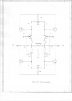
Just to illustrate why I like CFA, one of theamplifiers of mine that I prefer for Medium/high frequencies. A little basic CFA, with Diamond input, simple VAS and mosfet power devices.
Rock stable as you can see.
Harmonic distortion is -100dB at 1KHz, and -80dB at 20kHz. (when I say that actual devices are not fast enough ;-)
Thank to Fletcher et Munson to allow-me to sleep by night.
Of course, all input and output passive filters removed to impress the audience.
And i will keep the slew rate value for the marketing department ;-)
Attachments
Last edited:
Yes, for the full 100%.Our communication problems intervene again. Please consider the phrases in bold (you already used italics; I don't mean to be so emphatic.) From my reading we are saying the same thing. Let me rephrase: Given any point within a given circuit, the application of DIT will determine the DFM at that point. Do you agree with this statement?
Thank you for helping to sharpen the definitions.
Hans
Were the engineers before 1982 not clever enough to accurately analyze the general behavior of the the not-yet-called CFAs ? Note that the most notorious of them completely disagree on both points, semantic and technical, with the naming of CFA when it appears.
But today's brilliant engineers, educated at university and not very independant of mind, deliberatly ignore the previous generation which was much more inventive. Nertheless and happily, some of the current generation cunningly admit that the CF operation is more subtle than what the name and the "concept" suggest.
Lets make this crystal clear: the concept of CFA as defined by the IC industry is here to stay. While from a strictly academic perspective there is no need for any "current feedback" to analyze and and derive the CFA small signal properties, in the current body of knowledge assimilated since 1982(?) this concept reached a level of acceptance that does not leave room for any further debate.
The statement "CFAs don't exist" is as logical as stating that a tomato doesn't exist, only a tomatoe does.
I would be very curious though to find who came up in 1982(?) with the CFA concept, an engineer or a marketing guy with basic engineering understanding (rare breed today, I guess).
Last edited:
You mean the CFA name ? Because the concept was used by dinosaurs and I'm not sure that was the cause of their disappearance.I would be very curious though to find who came up in 1982(?) with the CFA concept, an engineer or a marketing guy with basic engineering understanding (rare breed today, I guess).
My greatest achievements in the last 8 years is being on the cover of the "Queen Elizabeth Theatre Toronto Canada" King Crimson album 😀.
And some additions to my lab, which is now capable of every electrical measurement known to men, from 1uHz to 40GHz, and down to -140dB distortion and noise (the microscope is showing my age 🙂) But somehow I don't believe a 40GHz wideband audio amplifier would win the Absolute Sound prize, though.
The rest are details 😛.
I cannot help but stare in horror at the very bent table top in the back corner and wonder how many tears there may be when that cheap particle board goes kaput. But that is quite the equipment rack.
I feel much more uncomfortable with the proposed analysisesForr, It seems CFA operation has been discussed here in all and every détails and that you are stuck by a simple semantic obstacle.
Good teachers do care. In science, words must have precise and non-ambiguous meanings. CFA is emblematic of what should be avoided.In French, some brand names are used to define objects, like "Frigidaire" ou "mobylette". Who cares, as long as everybody know what object is designed by those "sounds"/"letters" ?
One determines the other. What does determine the output (collector) current of an input stage ?So, why don't you forget this voltage and current names? Currents and voltages are two ways to look at the same physical phenomena: the way electrons flow in a circuit. That is resumed in a very simple formula: V=ZI.
Some engineers say that the beta is the predominant factor because that's how it is (or was, I hope it's not anymore like that) tought during their studies.I will not make you insult to remind you how a transistor works, nor how we analyze the poles in a closed loop.
On both CFA and CFA, there is a transistor supplying a current under the control of... (well, I won't say it once again, I am sufficiently often accused to repeat myself too often)All the answers on the differences between these two topologies are summarized comparing what happens in a "long tailed pair" and in a simple transistor, mounted in common emitter, on which one makes vary *current* between emitter and base (and their consequences on the current that flows in the collector) applying a tension to the emitter (as you like to think ;-).
Old = long before the second world war. Like Me Jourdain, people have used CFAs without knowing it.It is a very old and smart idea, to use the same tube working in common cathode for the +input and in common anode for the inverting one.
tension (french) = voltage (english)Hoping that my poor English will all make-you laugh ;-)
voltage (french) = nombre de volts permettant le fonctionnement d'un appareil électrique (french)
Precise meanings !
I cannot help but stare in horror at the very bent table top in the back corner and wonder how many tears there may be when that cheap particle board goes kaput. But that is quite the equipment rack.
It won't - that IKEA cheap table has two extra metal feet right in the middle to sustain the load. I'm still waiting to find a source of free racks with shelves/rails that can be dismantled for transportation. Not much luck here in Toronto, plenty of free racks but nothing that I can move in my basement without blood, sweat and tears. And I need at least 8.
Last edited:
You mean the CFA name ? Because the concept was used by dinosaurs and I'm not sure that was the cause of their disappearance.
Not sure what you mean or ask here, sorry.
Please, read the disclaimer and forgive-me. ;-)tension (french) = voltage (english)
voltage (french) = nombre de volts permettant le fonctionnement d'un appareil électrique (french)
Precise meanings !
(But, once again, you seem more interested in form than in substance ;-)
Last edited:
In CFA reducing THD at 1 MHz, means consequently THD at 1 kHz will decrease too?
By the same amount. Which raises the question if CFAs have any advantage in audio amplifiers. I would say no, but who am I to to open this can of
worms 😀.
I think that depends also on how you do that 1MHz reduction. Just increasing the loop feedback should decrease it at all frequencies, but
maybe there's another way that works different. What did you have in mind?
Jan
From a practical point of view I'm doing just that for quite some time, using 1 MHz test signal only, which significantly simplifies the whole CFA compensation procedure. No fancy AP test equipment needed, nor constantly jumping from audio to RF BW to see unwanted artefacts.
The main objective is straightforward, to wipe out all harmonics of 8 Ohm loaded 1 MHz sine test signal from a regular Tek FFT screen. -80 dB FFT bottom floor qualifies perfectly for THD-1MHz measurements, timebase is set in the same 100 ns scope region for the signal as well as artefacts observation, also SR rise/fall time measurements, etc. In short everything just folds together at MHz test region into an easy to make compensation procedure and I have to admit I'm enjoying doing it.
It's also much faster to set the correct compensation scheme to get lowest THD-1MHz. Excluding VAS Miller caps from the picture leads CFA into a sub ppm THD-20 region easily.

Don't you have a humor measurement device in your LAB that will haunt my nights ?Not sure what you mean or ask here, sorry.
Do not leave industry dictate its science, we now know how it costs to the planet. Inform involved people of the incongruities !Lets make this crystal clear: the concept of CFA as defined by the IC industry is here to stay. While from a strictly academic perspective there is no need for any "current feedback" to analyze and and derive the CFA small signal properties, the current body of knowledge assimilated since 1982(?) this concept to the level of acceptance that does not leave room for any further debate.
Attached image : I think the author is John Curl.
Attachments
- Home
- Amplifiers
- Solid State
- Current Feedback Amplifiers, not only a semantic problem?