What I learned. ( what I remember anyway ) If you look at the semiconductor physics a BJT is a current driven device.
Ic=beta x Ib
It's the electrons crossing the B-E junction that multiply the carriers across the C-E junction. On the other hand, the most accurate BJT equation is
Ic=Icss e*Vbexxx.
A fact that seems to have been missed is that the CFA circuits (in the sense of having a Low Impedance Inverting Input) do not necessarily rely on bipolar transistors. They can be built with FETs which are undoubtedly transconductance devices.
This simplifies the basic theorical analysis (I am tempted to say the intellectual approach) of the push-pull CFA topology because the input stage only needs two complementary FETs, the current across them being Vgs voltage driven.
Another difference or two
But there is another difference in the CFA for audio power amps -- there are only two stages and not 3 like standard VFA power amps and IC opamps.
This makes them easier to compensate and they can drive capacitive loads - not like the 3 stage standard VFA which needs an output inductor to drive capacitive loads and speaker cables.
Why not make audio power VFA's with two stages? Then it can be as stable as a CFA, EG like Michael Renardson's MJR7 MJR7-Mk5 Mosfet Power Amplifier Design Notes which doesn't have the usual input stage; the input goes straight to the so-called 'VAS'. This was the way with early Lin amps before they added the differential input stage.
The comparison by Andrew Russell http://hifisonix.com/wordpress/wp-content/uploads/2014/01/CFA-vs-classic-Lin-VFA-topology.pdf favours CFA for bandwidth but at the expense of distortion. If the comparison was between a CFA and a two stage VFA like the MJR7 then the differences may vanish. Anyone like to do the comparison?
As for the maths for feedback analysis of the CFA I notice a CFA is basically like Fig 6 in Leach 'series-shunt' example https://linearaudio.nl/sites/linearaudio.net/files/leach_feedback_basics.pdf, except CFA IC's have a voltage buffer giving higher gain -- so the CFA is still the same feedback type as a VFA shown in Fig 4 where the non-inverting VFA also uses 'series-shunt'.
Back to the CFA's lower Z on the inverting input, it means lower Rf and Rg values are needed and this helps video amps, but it's not a huge benefit for audio (see Post #61). That leaves me thinking the advances with CFA's come down to using 2 stages rather than 3 making them easier to compensate for driving capacitive loads -- to me that is a huge benefit for audio. I assume UL-distortion is not necessary for a good sounding audio amplifier; it is relatively easy to get a 2 stage amp sound free of crossover distortion, my CSD amp in Linear Audio Vol.13 was the latest, see my sign link. Other factors like soft clipping and current drive of speakers is a far higher priority for me for power amplifiers.
One final piece in the jigsaw, about the development of the CFA, is that VFA IC's did not have fast PNP's until the 1990's so they couldn't make really fast fully complementary opamps. When the CFA was developed, fast PNP's had just arrived, making them faster than VFA's. Applying the same methods to VFA's you get similar speeds as CFA's - read the IEEE Erik Brauun paper, last line of the summary, it's on Jan's website https://linearaudio.nl/sites/linear...nalysis-of-Transimpedance-CFB-OA-Circuits.pdf
So the 'CFA' name is not about a different feedback arrangement - it's about a different internal topology. Convert the CFA topology with two high Z inputs and you have a new VFA topology with pretty much the same performance figures.
Attached are some fast VFA's -- they are CFA's with two high-Z inputs. And there are still only 2 stages to compensate. Walt Jung's book is here http://www.kelm.ftn.uns.ac.rs/literatura/mpi/pdf/Op Amp Applications Handbook.pdf
BTW I found Scott Wurcer's tiny CFA http://www.diyaudio.com/forums/atta...2874415-fully-complementary-ad797-blesser.jpg; it's a little gem. I have simulated it and has great potential for audio power amps and it works great with MOSFET power transistors as well. The post is http://www.diyaudio.com/forums/solid-state/306797-fully-complementary-ad797-3.html#post5059708
.. The internal workings are of current transfers, low Z and thus fast stray/device C charge and therefore high BW and SR. etc.
But there is another difference in the CFA for audio power amps -- there are only two stages and not 3 like standard VFA power amps and IC opamps.
This makes them easier to compensate and they can drive capacitive loads - not like the 3 stage standard VFA which needs an output inductor to drive capacitive loads and speaker cables.
Why not make audio power VFA's with two stages? Then it can be as stable as a CFA, EG like Michael Renardson's MJR7 MJR7-Mk5 Mosfet Power Amplifier Design Notes which doesn't have the usual input stage; the input goes straight to the so-called 'VAS'. This was the way with early Lin amps before they added the differential input stage.
The comparison by Andrew Russell http://hifisonix.com/wordpress/wp-content/uploads/2014/01/CFA-vs-classic-Lin-VFA-topology.pdf favours CFA for bandwidth but at the expense of distortion. If the comparison was between a CFA and a two stage VFA like the MJR7 then the differences may vanish. Anyone like to do the comparison?
As for the maths for feedback analysis of the CFA I notice a CFA is basically like Fig 6 in Leach 'series-shunt' example https://linearaudio.nl/sites/linearaudio.net/files/leach_feedback_basics.pdf, except CFA IC's have a voltage buffer giving higher gain -- so the CFA is still the same feedback type as a VFA shown in Fig 4 where the non-inverting VFA also uses 'series-shunt'.
Back to the CFA's lower Z on the inverting input, it means lower Rf and Rg values are needed and this helps video amps, but it's not a huge benefit for audio (see Post #61). That leaves me thinking the advances with CFA's come down to using 2 stages rather than 3 making them easier to compensate for driving capacitive loads -- to me that is a huge benefit for audio. I assume UL-distortion is not necessary for a good sounding audio amplifier; it is relatively easy to get a 2 stage amp sound free of crossover distortion, my CSD amp in Linear Audio Vol.13 was the latest, see my sign link. Other factors like soft clipping and current drive of speakers is a far higher priority for me for power amplifiers.
One final piece in the jigsaw, about the development of the CFA, is that VFA IC's did not have fast PNP's until the 1990's so they couldn't make really fast fully complementary opamps. When the CFA was developed, fast PNP's had just arrived, making them faster than VFA's. Applying the same methods to VFA's you get similar speeds as CFA's - read the IEEE Erik Brauun paper, last line of the summary, it's on Jan's website https://linearaudio.nl/sites/linear...nalysis-of-Transimpedance-CFB-OA-Circuits.pdf
So the 'CFA' name is not about a different feedback arrangement - it's about a different internal topology. Convert the CFA topology with two high Z inputs and you have a new VFA topology with pretty much the same performance figures.
Attached are some fast VFA's -- they are CFA's with two high-Z inputs. And there are still only 2 stages to compensate. Walt Jung's book is here http://www.kelm.ftn.uns.ac.rs/literatura/mpi/pdf/Op Amp Applications Handbook.pdf
BTW I found Scott Wurcer's tiny CFA http://www.diyaudio.com/forums/atta...2874415-fully-complementary-ad797-blesser.jpg; it's a little gem. I have simulated it and has great potential for audio power amps and it works great with MOSFET power transistors as well. The post is http://www.diyaudio.com/forums/solid-state/306797-fully-complementary-ad797-3.html#post5059708
Attachments
BTW I found Scott Wurcer's tiny CFA
Funny that Barry gave that idea away, it was so long ago it would have been patentable.
BTW in the basic CFA the displacement current in the comp cap flows in the feedback resistor, that alone justifies the name since once you realize this the main differentiating features are obvious.
But there is another difference in the CFA for audio power amps -- there are only two stages and not 3 like standard VFA power amps and IC opamps.
This makes them easier to compensate and they can drive capacitive loads - not like the 3 stage standard VFA which needs an output inductor to drive capacitive loads and speaker cables.
That leaves me thinking the advances with CFA's come down to using 2 stages rather than 3 making them easier to compensate for driving capacitive loads -- to me that is a huge benefit for audio. I assume UL-distortion is not necessary for a good sounding audio amplifier; it is relatively easy to get a 2 stage amp sound free of crossover distortion, my CSD amp in Linear Audio Vol.13 was the latest, see my sign link.
So the 'CFA' name is not about a different feedback arrangement - it's about a different internal topology. Convert the CFA topology with two high Z inputs and you have a new VFA topology with pretty much the same performance figures.
Attached are some fast VFA's -- they are CFA's with two high-Z inputs. And there are still only 2 stages to compensate. Walt Jung's book is here http://www.kelm.ftn.uns.ac.rs/literatura/mpi/pdf/Op Amp Applications Handbook.pdf
-------------------------------------------------------------------------------------------
While being called every name in the book, I made same points and I had this argument with Waly a year or two ago..... IMO, Current-Mode Amps are easier to compensate. And fewer stages is always a plus IMO.
It Is the internal topology that hasn't been appreciated -- too much talk about FB. The CMA can also have very low distortion, I mean Very.
THx-RNMarsh
Last edited:
I agree with some of the previous posts - some interesting points raised.
However, the best way to look at this whole CFA/VFA thing is to draw a continuum. Classic CFA on one side (2 gain stages, moderate open loop gain, ergo low loop gain etc) and classic VFA on the other (LTP input, 3 gain stages, moderate to high open loop gain, ergo higher loop gains).
As you increase the loop gain of the CFA by design (e.g. helper transistor in the VAS, EF2 or EF3 OPS), its OLG and LG behaviour migrates towards the VFA. The OLG bandwidth decreases as the loop gain goes up. Very simple to test this in the sim and do the attendant gain/phase plots.
The sx-and nx-Amps were conceived as classic simple CFA designs, both used MIC and traded very wide bandwidths, low OLG and LG's for higher distortion. - 3dB Loop gain bandwidth on the class A sx-Amp is 60 kHz while on the nx-Amp which has about 30 dB more loop gain, its 8 kHz.
Note, you can get high loop gain bandwidths (10's of kHz) on VFA and high gain CFA as well by using two pole comp or OIC - and it works very well if that is what you want. However, in high gain CFA's you have an amplifier that more resembles a VFA in its behaviour - its a grey 'performance overlap' area.
Re the output inductor. You can get away without it in a classic CFA, although I did include it on both the sx and nx designs. However, in high OLG CFA designs, you will need the output L OR heavier compensation i.e. closing the ULGF lower. The predominant contributor to phase shift in any competently designed audio amp is in the OPS - not the small signal stages - and dealing with that is where the lions share of the focus has to be in comp design.
Classic CFA amps are easier to comp, but high loop gain CFA's no easier than comparable VFA's. In low OLG CFA's like the sx-Amp, the OPS pole falls below 0 dB above the ULG. Compensation is therefore more a matter of limiting the bandwidth to avoid problems with parasitics - you can see this on the compensation design plots for the sx-Amp. On a comparable VFA, the OPS pole falls above 0dB and below the ULGF - add a capacitive load, and it migrates down in frequency and the phase margin decreases - instability beckons.
There seems to be a lot of discussion about exactly what a CFA is - some deny they even exist (remember MK ) and so on. I think the best way to understand the difference is in how the input stage output current behaves into the VAS. In a classic VFA its limited by the diff amp tail current and all the diff amp does is steer a portion of the tail current (usually a current source) into or away from the VAS input. In a classic CFA, the maximum current into the VAS is determined by the peak output voltage and the feedback resistor. And this is the primary reason why classic CFA's are faster (slew rate and BW) than their classic VFA counterparts - the current into the VAS input can be as much as 10x higher in the CFA. Note carefully though, this only applies to classic exemplars of either topology. Once you raise the loop gain of the CFA, it begins to resemble a VFA and the higher slew rates and BW's not as evident.
Again, for the record (and perhaps the 3rd or 4th time in the last 4 years) I have designed in both topologies - details on my website. I have never claimed one is fundamentally better than the other anywhere. I have settled on CFA amps because I like them and I can make them perform to the specifications I set out to achieve - nothing more than that. The most important thing as designer is to settle on an approach and then perfect it. Whatever path you choose, you can usually get good results.
Last edited:
A good source for information on the topic: Evolution of high-speed operational amplifier architectures
S
S
This makes them easier to compensate and they can drive capacitive loads - not like the 3 stage standard VFA which needs an output inductor to drive capacitive loads and speaker cables.
I disagree. CFAs are easy to compensate, but not easier to optimally compensate (compared to a VFA). Slapping a shunt compensation is not optimal in my book, although this seem to be the most common CFA compensation method, at least in the audio realm.
On the other side, some compensation methods are not available for CFAs: e.g. lead compensation (or phase correction) is a big nono.
Not sure where you got the CFA tolerance to capacitive loads. For all I can tell, they are actually much fussy about capacitive loads, mainly due to their higher bandwidth. And the capacitive load isolation is required as well, no difference to a regular VFA, the output impedance is still inductive and can resonate with a capacitive load, if not damped is a perfect oscillator.
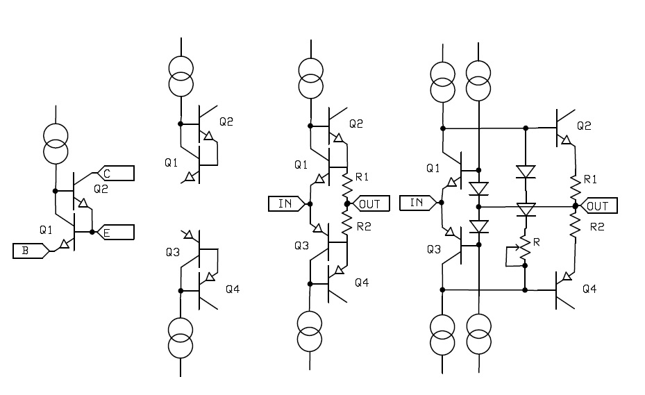
Do you consider that in a CFA toplogy circuit, the input and current mirror are only one stage ?But there is another difference in the CFA for audio power amps -- there are only two stages and not 3 like standard VFA power amps and IC opamps.
A CFA toplogy input stage ends at the collector output of the transistors of the inverting input. The second stage begins at the load of these collectors (and they are not necessarily current mirrors) so I see CF topology Amplifiers as 3 stages, just like circuits with the VFA topology.
so I see CF topology Amplifiers as 3 stages, just like circuits with the VFA topology.
Yes, the Gosser topology does and has huge slew rates and BW's. IMO this path of discussion is an unnecessary sideshow.
This is the subject of the thread, it is not the comparison of the strenghts and witnesses of the C and V feedback topologies.There seems to be a lot of discussion about exactly what a CFA is
Reasons have been given. The main one is that feedback circuits are based on a difference at their input and you can only substract values of the same kind.- some deny they even exist (remember MK ) and so on.
I wonder what kind of feedback is in function with a diamond input when very low values are given to the resistors of the feedback network.
Let's say 9 and 1 Ohm for a gain of 10. The diamond inverting input has a markedly higher impedance than the output impedance of the feedback network divider, so, albeit having no buffer, it is mainly voltage driven.
Yes, the Gosser topology does and has huge slew rates and BW's. IMO this path of discussion is an unnecessary sideshow.
Indeed it is. But it only keeps coming up because there's problem in that many struggle to understand how they work. That's why I wrote the CFA/VFA comparison article.
We should also keep in mind the application here on the forum is for DIY amplifiers. People don't have access to the kind of devices and circuit/process tricks you find in a fab and that help support huge SR's and BW's. You're never going to successfully build a discrete 1GHz BW 6000 V/us amp.
Last edited:
Ovation High Fidelity - Power Amplifiers
So CFAs are preferred because they provide, among others, low, constant feedback across the audio band. Isn't it funny how the "wide open loop bandwidth" and "low feedback" comes into discussion as soon as advertising an audio amplifier is involved? Mr. Curl should be proud of his disciples...
The result are amplifiers [CFAs] that apply the same low level of feedback across the critical audio band frequencies and feature wide loop gain bandwidths, high slew rates and low distortion.
So CFAs are preferred because they provide, among others, low, constant feedback across the audio band. Isn't it funny how the "wide open loop bandwidth" and "low feedback" comes into discussion as soon as advertising an audio amplifier is involved? Mr. Curl should be proud of his disciples...
Last edited:
headphone amp TPA6120 is CFA and have great parameters and also is very fast ... plus sounds great - and this is most important in audio, how it sounds .... I am for CFA or VFA with great sound, I hate CFA and VFA with bad sound result
While being called every name in the book, I made same points and I had this argument with Waly a year or two ago..... IMO, Current-Mode Amps are easier to compensate. And fewer stages is always a plus IMO.
It Is the internal topology that hasn't been appreciated -- too much talk about FB. The CMA can also have very low distortion, I mean Very.
THx-RNMarsh
I missed your posts are year or two ago. Do you have a link to share?
A good source for information on the topic: Evolution of high-speed operational amplifier architectures S
Thanks for that link. A gem of an article. I lost track of my copy.
...Not sure where you got the CFA tolerance to capacitive loads. For all I can tell, they are actually much fussy about capacitive loads, mainly due to their higher bandwidth. And the capacitive load isolation is required as well, no difference to a regular VFA, the output impedance is still inductive and can resonate with a capacitive load, if not damped is a perfect oscillator.
Agreed. But that's with IC CFA's -- the parasitic inductance on the output pin is a big problem, creating ringing from 500MHz even with SOIC's (see Smith Fig 16 and Fig 17, link given above by sf1412, like 3nH of PCB track to the output and 2pF of PCB track on the way).
But I am interested in audio power amplifiers, designing for say 2uF almost purely capacitive loads for driving an ESL (with transformer). With the CFA, 2uF load get's transformed by the output buffer beta's to a capacitance in parallel with the internal compensation capacitor (Ccomp Fig 3, Smith). This reduces the effective compensation break frequency. With a two-stage topology this is stable over a wide range of Cload. This works best with the shunt Ccomp at the input of the buffer. Anyone else noticed this? Maybe I shouldn't give away this little secret?😉
Now with a VFA 3 stage topology like the traditional Lin (VFA) topology with typically Miller compensation, adding load capacitance causes oscillation unless the load capacitance is decoupled by an output inductor or resistor.
Do you consider that in a CFA toplogy circuit, the input and current mirror are only one stage ?
A CFA toplogy input stage ends at the collector output of the transistors of the inverting input. The second stage begins at the load of these collectors (and they are not necessarily current mirrors) so I see CF topology Amplifiers as 3 stages, just like circuits with the VFA topology.
I use "2-stage" loosely to mean the number of major poles up to the roll-off frequency for the power amp. Not in the strict topological sense.
Like when you add a cascode to say a 'VAS', you still treat it as one stage since there is still one main pole and the cascode's pole is insignificant for closed loop stability.
With the CFA, 2uF load get's transformed by the output buffer beta's to a capacitance in parallel with the internal compensation capacitor (Ccomp Fig 3, Smith). This reduces the effective compensation break frequency. With a two-stage topology this is stable over a wide range of Cload. This works best with the shunt Ccomp at the input of the buffer.
There are several issues here, and me being still half asleep I'll address them quickly:
- the output buffer transforming the capacitive load. Your description is correct, and precisely the reason why a 2uF capacitive load is never an issue for stability. CFA or VFA, the critical capacitive load for a power amp is anywhere between 10nF and 100nF. Easy to verify by simulation.
- I don't see any first order reason why CFAs would behave better for large capacitive loads, compared to a VFA.
- yes, the transformed capacitive load loads the (usually) transimpedance gain stage, and it adds to an existing shunt compensation. But, as I said, shunt compensation is in 99% of the cases suboptimal, both in CFAs and VFAs, one reason is it does not allow lowering the transimpedance stage output impedance, like e.g. Miller compensation, therefore missing an opportunity to lower the open loop distortion.
also the ESL stepup xfmr winding R and leakage inductance give fine isolation, doesn't look anything like a low esr, esl extended foil 2 uF cap by typical ugif
"With the CFA, 2uF load get's transformed by the output buffer beta's to a capacitance in parallel with the internal compensation capacitor (Ccomp Fig 3, Smith). This reduces the effective compensation break frequency. With a two-stage topology this is stable over a wide range of Cload. This works best with the shunt Ccomp at the input of the buffer. Anyone else noticed this? Maybe I shouldn't give away this little secret?"
If this is allowed to happen, the loop gain bandwidth is capacitance load dependent and therefore all over the place. If you want to minimize distortion across the whole audio band, surely you want to maximize feedback? An output coupling inductor is an extremely robust way of isolating the amp - and the effects you note - from the load. In a classic CFA you will have lower loop gain, but over a wider bandwidth. I would not think you could afford to reduce the loop gain bandwidth without sacrificing HF distortion in this case.
Classic (low loop gain, wide BW) audio amplifier CFA's are load tolerant because the OPS pole falls below 0dB and above the ULGF. The trick is to make sure under worst case load conditions, the OPS does not migrate down and therefore below the ULGF. This OPS pole migration mechanism is much more evident in high loop gain amplifiers - CFA and VFA - because the OPS pole lies above 0dB. The old way to deal with this was with pole-splitting and load isolation through an output inductor which allows more feedback to be applied.
Last edited:
I agree with that.I use "2-stage" loosely to mean the number of major poles up to the roll-off frequency for the power amp. Not in the strict topological sense.
Like when you add a cascode to say a 'VAS', you still treat it as one stage since there is still one main pole and the cascode's pole is insignificant for closed loop stability.
If the load of the input stage is resistive and followed by an EC, it becomes a 3 stages topology.
Note that Samuel Groner does not count the output stage in the number at the end of this document
http://www.nanovolt.ch/resources/ic_opamps/pdf/opamp_distortion.pdf
Semantics again.
- Home
- Amplifiers
- Solid State
- Current Feedback Amplifiers, not only a semantic problem?