I have no disagreement with this expression which is not your definition but the standard one.Since you reject my definition of and means of testing L, how would you define and test it?
I only have doubt on the validity of your calculated current loop gain, for which you have to define a current gain and a current feedback transfer.
of course.Yes. This is akin to G (but for current), not L.
May be I missed it, but I never saw the justification of the expressions used for the loop gains."unless demonstration"? please explain.
No I didn't say that.You are saying that a loop gain is the ratio of two loop gains. This is a useless, circular definition.
The loop gains are clearly defined, but you have not demonstrated that the expressions you use as Ti and Tv are equivalent to their definition.A feedback amplifier has a loop, an input signal, an output signal, and a load. There is the transfer gain, which relates the input and output signals, and a loop gain, which is defined and tested as I have shown. These are two different things. Again, how would you define and test loop gains, voltage and current?
I think you wanted to say inverting input ? If yes I agree, it is an error that I have corrected.A voltage appears at the non-inverting input of the current source configuration due to the non-zero input impedance. We can argue about whether it is "applied", but it certainly arises.
As far as I know, with "normal" pressure and temperature conditions, it is not so easy to have voltages without currents or currents without voltages.And a current flows into the input of what you refer to as the voltage source (configuration). In that configuration, I(en) = I(in) - I(outn). Denying this relationship denies Conservation of Current, which I doubt that you are prepared to do. The relationship between I(en) and I(outn) establishes current feedback. This is clearly not "pure voltage feedback."
Alternatively, you can find the Thevenin equivalent of In, Outn, Rf and Rg. The voltage source VT = (Rf In + Rg Outn) / (Rf + Rg). VT is connected to en by Rfg = Rf Rg / (Rf + Rg). Surely you will not deny Thevenin's Theorem! A current flows between VT and en. Outn contributes to VT. This establishes a relationship between I(en) and Outn, one of current feedback. Again, this is clearly not "pure voltage feedback."
The classification I made (on which you certainly disagree) is based on what I said on my last post.
Current feedback <=> feedback controlled by current sources
Voltage feedback <=> feedback controlled by voltage sources
Incidentally, your analyzis of my position in relation to the principles of electricity are very interesting.
Name is changed and inverting input of the current source is now connected to ground.Thanks for the J505 current source. Kindly post the CR en courant.asc file.
Attachments
I have no disagreement with this expression which is not your definition but the standard one.
I only have doubt on the validity of your calculated current loop gain, for which you have to define a current gain and a current feedback transfer.
of course.
By using the word "my" I did not mean to claim that I originated the definition.
The current gain is the current transfer function. Both are equal to the ratio of the return to the forward current. You can simulate the circuit and confirm that my expression for the current loop gain is correct. Please see my next comment.
May be I missed it, but I never saw the justification of the expressions used for the loop gains.
No, you didn't miss it. I thought it was obvious, but I have been told by someone else that it is not, so I apologize for not providing it before. It's in the attachment.
No I didn't say that.
You said, "A current loop gain would be the ratio between an open loop current gain and a closed loop current gain..." OK, consider a zero output impedance gain block with an open loop voltage gain of a and a feedback factor of b. If we substituted "voltage" for "current" in what you just said, the loop gain would be a divided by a / (1 + a b) = 1 + ab. Where does the extra "1" come from? You need to derive your claim.
The loop gains are clearly defined, but you have not demonstrated that the expressions you use as Ti and Tv are equivalent to their definition.
I had not done so, but I now show this in the attachment.
I think you wanted to say inverting input ? If yes I agree, it is an error that I have corrected.
Yes, thanks for correcting my error. But by applying feedback to the non-inverting input, the circuit is the same as if you substituted a VFA for the CFA (other than the inverting input ground current). What's the point?
...The classification I made (on which you certainly disagree) is based on what I said on my last post.
Current feedback <=> feedback controlled by current sources
Voltage feedback <=> feedback controlled by voltage sources
I understand, but see no reason to accept your re-definitions of the term "feedback". I could quote various definitions found in technical and non-technical dictionaries which are inconsistent with your choice, and I shall if you request it. But I think it would be better if you could quote an authoritative source that defines "feedback" in a manner that supports your classification.
Incidentally, your analyzis of my position in relation to the principles of electricity are very interesting.
You comment seems to be a way to sidestep the challenges I wrote to your position.
Name is changed and inverting input of the current source is now connected to ground.
Now I need the symbol file for diam00.asc.
Attachments
OK, consider a zero output impedance gain block with an open loop voltage gain of a and a feedback factor of b. If we substituted "voltage" for "current" in what you just said, the loop gain would be a divided by a / (1 + a b) = 1 + ab. Where does the extra "1" come from? You need to derive your claim.
I need to add a comment to one I made above in Post 2602. Please reference the bold text above. I am trying to interpret your claim, and I'm not sure how to do it. An alternate interpretation could be
the loop gain would be (a b) divided by a / (1 + a b) = b (1 + ab). I believe that we can agree that the b^2 doesn't make sense. I recommend that you derive your claim.
The current gain is the current transfer function. Both are equal to the ratio of the return to the forward current. You can simulate the circuit and confirm that my expression for the current loop gain is correct. Please see my next comment.
If current gain is the current transfer function (current closed loop gain), there is no current feedback.
No, you didn't miss it. I thought it was obvious, but I have been told by someone else that it is not, so I apologize for not providing it before. It's in the attachment.
Nothing is obvious in real life.
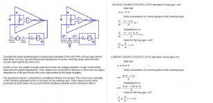
1) I can't accept any calculation or conclusion drawn from the model you attached. It doesn't represent a generalization of existing VFA or CFA, as it is not possible to say that
vout = i(in-)*rd*A where rd is the differential input impedance and A the voltage gain of the amplifier, represents a general behaviour of amplifiers.
2) The starting point of your calculation is that the current loop gain is ir/if, it is that point I disagree.
Then I never wrote that loop gain is the ratio of two loop gains. Open loop gain is not a loop gain.You said, "A current loop gain would be the ratio between an open loop current gain and a closed loop current gain..." OK, consider a zero output impedance gain block with an open loop voltage gain of a and a feedback factor of b. If we substituted "voltage" for "current" in what you just said, the loop gain would be a divided by a / (1 + a b) = 1 + ab. Where does the extra "1" come from? You need to derive your claim.
Why do you change the meaning of what I write ?
I don't think you can simply substitute "voltage" by "current" in your expressions, for example, what is the current feedback factor ?
Yes, thanks for correcting my error. But by applying feedback to the non-inverting input, the circuit is the same as if you substituted a VFA for the CFA (other than the inverting input ground current). What's the point?
I don't understand, where do I apply feedback on a non inverting input ?
I understand, but see no reason to accept your re-definitions of the term "feedback". I could quote various definitions found in technical and non-technical dictionaries which are inconsistent with your choice, and I shall if you request it. But I think it would be better if you could quote an authoritative source that defines "feedback" in a manner that supports your classification.
I never re-defined the term feedback. Once again you modify what I say. I just propose a way to classify "voltage feedback" and "current feedback", which, as far as I know have no official definitions. Thanks to tell me if it is not the case.
You comment seems to be a way to sidestep the challenges I wrote to your position.
You go astray
If current gain is the current transfer function (current closed loop gain), there is no current feedback.
Your conclusion seems illogical to me. Kindly explain your logic. If the transfer function of a network has a finite, non-zero value, then it modifies and conveys a signal from the network input to its output. In the case I am discussing, the network is a continuous loop rather than one with a distinct beginning and an end. A signal is inserted, modified and returned to its point of origination. The modified signal is fed back. You don't need a dictionary to know that if something is fed back, then it is part of a feedback phenomenon.
1) I can't accept any calculation or conclusion drawn from the model you attached. It doesn't represent a generalization of existing VFA or CFA, as it is not possible to say that
vout = i(in-)*rd*A where rd is the differential input impedance and A the voltage gain of the amplifier, represents a general behaviour of amplifiers.
You may have forgotten that in Post 2575, in response to your concern, I granted your point about differential input impedance. However, there is still in any real op amp a finite, non-zero, ground-referenced impedance looking into the inverting input when the non-inverting input is grounded. For a voltage to arise across the two inputs, a current must flow through this impedance. And either that voltage is amplified and converted into another voltage (for voltage output amplifiers), or the current is converted through an impedance Z. There are no other possibilities, and both are discussed in 2548.
But if your claim really is true, then it should be simplicity in itself for you to find an op amp whose AC performance you can simulate and present here to demonstrate that it does not follow the model that you reject. I challenge you to either do so, or to accept the model.
2) The starting point of your calculation is that the current loop gain is ir/if, it is that point I disagree.
Here I suspect that there is a problem with words. The current gain around the loop is clearly ir/if. Insert a current into the loop at the inverting input. A portion of it becomes the forward current if. The loop modifies it and returns it, or feeds it back, as ir. The analysis and any simulation you care to perform will confirm this. If a signal is modified, looped around, and fed back to its starting point, then there is feedback. The very meaning of the words prevent us from escaping this conclusion.
Then I never wrote that loop gain is the ratio of two loop gains. Open loop gain is not a loop gain.
Why do you change the meaning of what I write ?
I don't think you can simply substitute "voltage" by "current" in your expressions, for example, what is the current feedback factor ?.
I'm trying and apparently failing to understand the meaning of what you wrote. And you are ignoring the question I asked you about the voltage gain around the loop.
I don't understand, where do I apply feedback on a non inverting input ?
I am running blind here; I have to guess because I need to repeatedly ask you to provide missing files to run your simulations. And I still can't run your complete sim. So maybe you don't apply feedback to the non-inverting input, and maybe you do. But I still don't have the latest missing file, so I can't tell for sure; I can only guess until and unless you provide what I've asked for.
I never re-defined the term feedback.
You did exactly that.
You did it when you "classified" voltage and current feedback. Another word for "classify" in this case is "define." You have apparently rejected all other possible "classifications". Because if you had not, you would have had to allow that other "classifications" could admit the possibility that the CFA, used as it is designed to be, could employ current feedback. But you reject that, right? So logically, you must reject other classifications of current feedback. How is that not defining current feedback?
I just propose a way to classify "voltage feedback" and "current feedback", which, as far as I know have no official definitions.
That may be one of the most - I don't even have a word for it - things that I have read on this thread to date. You state that "current feedback" has no "official definition." Yet at the same time you are willing to say that when we connect resistors between signal sources, the inverting input and the output of a CFA, we observe "pure voltage feedback" - which can only mean that there absolutely none of that which there is "no official definition" for - current feedback?
To sum up, it doesn't exist officially, so you make up your own "classification" for it, and then declare that it doesn't exist in a CFA as it was designed to be used.
Wow.
You go astray
You avoid the inconvenient questions.
There's still movement on this front, VFA fighting back and new products being introduced that blur the distinction between the two topologies.
Witness the OPA622, a CFA core plus two buffers. One buffer can be used to buffer the inv input, the other can buffer the CFA output. Together with some smart compensation you get benefits of VFA (low distortion & noise) with those of the CFA (high slew rate, gain-independent bandwidth).
À propos smart compensation: see Michael Steffes resurrected 1997 article on this, further closing the gap between the two topologies. It's an interesting opamp world out there.
Jan
Interesting... a feedback type-configurable device.
The only thing I'd add is that I would call the configuration that you cite for combined benefits a VFA, despite its CFA-like double-diamond input stage(s) and its CFA core. The manufacturer refers to it as such, and Middlebrook would confirm it. One way to explain this is that the bulk of the currents flowing in its input stages do not flow through its feedback input.
The only thing I'd add is that I would call the configuration that you cite for combined benefits a VFA, despite its CFA-like double-diamond input stage(s) and its CFA core. The manufacturer refers to it as such, and Middlebrook would confirm it. One way to explain this is that the bulk of the currents flowing in its input stages do not flow through its feedback input.
I'm not going there again ;-)
What I noted was the use of 'OTA' (operational transconductance amplifier) for the CFA core. I wonder why that hasn't stuck instead of CFA. We would have saved a lot of bandwidth and grief if it had!
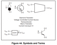
I have the feeling it is related to (healthy?) competition between groups or companies. The OPA860 and family for instance is consequently mentioned as an OTA. In the attached, from the data sheet, they list several terms and symbols for the same thing but studiously avoid 'CFA'.
TI against Comlinear/LTC? They are just like people ;-)
Jan
What I noted was the use of 'OTA' (operational transconductance amplifier) for the CFA core. I wonder why that hasn't stuck instead of CFA. We would have saved a lot of bandwidth and grief if it had!
I have the feeling it is related to (healthy?) competition between groups or companies. The OPA860 and family for instance is consequently mentioned as an OTA. In the attached, from the data sheet, they list several terms and symbols for the same thing but studiously avoid 'CFA'.
TI against Comlinear/LTC? They are just like people ;-)
Jan
Attachments
Jan, even more of an achievement is the supply current of only 5 mA.
And as far as I’m concerned, they may call it whatever they like, I could ‘t care less.
It’s just a fantastic product.
Hans
And as far as I’m concerned, they may call it whatever they like, I could ‘t care less.
It’s just a fantastic product.
Hans
Yes it is, they even pull out a new type of spec: bandwidth in MHz per mA supply current: 200MHz/5mA. Hilarious what they think of in the marketing dept!
BTW I was wrong, they do mention a 'CFA application' in a short paragraph.
Jan
BTW I was wrong, they do mention a 'CFA application' in a short paragraph.
Jan
Attachments
Last edited:
My impression is that TI uses the term CFA for an (OTA +output buffer) which is an understandable division of functions.
I'm not going there again ;-)
I can't imagine why...
What I noted was the use of 'OTA' (operational transconductance amplifier) for the CFA core. I wonder why that hasn't stuck instead of CFA. We would have saved a lot of bandwidth and grief if it had!
I'm not so sure. The OTA core could be used with a dual double diamond input stage or a classic long tailed pair. The "grief" has to do with whether the input stage presents bases or emitters to its inputs, not with the nature of the core.
"CFA" and "VFA" appear in a few figures; the phrase "current feedback" appears three times in the text and voltage feedback once. "Current feedback amplifier" and "voltage feedback amplifier" appear in the captions of several figures. To my mind, for what little it's worth (my opinion that is, not my mind), they are using the terms correctly.
My impression is that TI uses the term CFA for an (OTA +output buffer) which is an understandable division of functions.
An OTA is an Operational Transconductance Amplifier, a voltage-to-current device. This is a sensible name for a circuit if you differentially drive the bases of its two double diamond input stages. But how could such a device be called a CFA?
If instead you apply feedback to the emitter of a single double diamond input stage, then it is reasonable to call the device a CFA. But then it seems a bit of a problem to call the input portion an OTA.
Since feedback could be applied to either point, a better term for the input stage might have been Current Output Amplifier.
Chris,An OTA is an Operational Transconductance Amplifier, a voltage-to-current device. This is a sensible name for a circuit if you differentially drive the bases of its two double diamond input stages. But how could such a device be called a CFA?
If instead you apply feedback to the emitter of a single double diamond input stage, then it is reasonable to call the device a CFA. But then it seems a bit of a problem to call the input portion an OTA.
Since feedback could be applied to either point, a better term for the input stage might have been Current Output Amplifier.
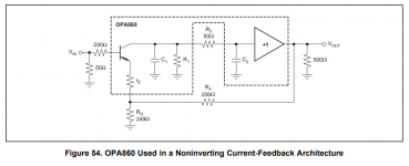
Have a look at fig 54 in TI’s OPA860 spec.
OTA + Buffer = CFA
That’s how they call it, the rest is history.
Hans
Chris,
Have a look at fig 54 in TI’s OPA860 spec.
OTA + Buffer = CFA
That’s how they call it, the rest is history.
Hans
Forgive me; I would not want to disabuse you of the Gospel According to T.I.
Figure 54 is indeed a CFA. But in that figure, do pins 2, 3 and 8 of the part constitute an OTA?
Well, there is a voltage at pin 2, but T.I. also proclaims that there is current feedback. So if the word from on high is that we have a voltage at one input and a feedback current entering the other, do we really have an OTA?
If the only pin 2 connection were to a grounded resistor and pin 3 were driven by a voltage, we'd indeed have an OTA.
The Marketeers had to call it something. But since it could be used in different ways, isn't something like "Current Output Amplifier" a better description of the ways that that portion of the part can be used?
Hi Chris,Forgive me; I would not want to disabuse you of the Gospel According to T.I.
Figure 54 is indeed a CFA. But in that figure, do pins 2, 3 and 8 of the part constitute an OTA?
Well, there is a voltage at pin 2, but T.I. also proclaims that there is current feedback. So if the word from on high is that we have a voltage at one input and a feedback current entering the other, do we really have an OTA?
If the only pin 2 connection were to a grounded resistor and pin 3 were driven by a voltage, we'd indeed have an OTA.
The Marketeers had to call it something. But since it could be used in different ways, isn't something like "Current Output Amplifier" a better description of the ways that that portion of the part can be used?
Every now and then there comes a point in time where you have to let things go and leave them for what they are.
Haven't we reached that point of no return ?
Hans
Courage is when you go ahead and change what needs to be changed. Acceptance is to leave things that you know you can't change.
Wisdom is to know the difference ;-)
Jan
Wisdom is to know the difference ;-)
Jan
Hi Chris,
Every now and then there comes a point in time where you have to let things go and leave them for what they are.
Haven't we reached that point of no return ?
Hans
If we have, why did you comment? I merely replied.
If we have, why did you comment? I merely replied.
It was nothing but a friendly advise out of respect for you.
Hans
- Home
- Amplifiers
- Solid State
- Current Feedback Amplifiers, not only a semantic problem?