You can run the buffer transistors at a higher emitter current - that will also help with this problem - but I have not quantified that or sim'd it. If you carefully select the type of transistors, that can also mitigate the problem - so a type number with a higher Vbe can be used for the input buffer, and the lower Vbe type for the level shifter.
I cannot comment on the Marantz without seeing the circuit. We also don't know what their test/selection procedures are.
Bottom line is if you run both the input buffer and level shifter transistors at the same current (~1mA in this case) and the Vbe of the input buffer transistor(s) is higher than the level shifters, you will have imbalance issues, and in severe cases, one or both of the level transistors will be cut off. This is what happened on the early nx-Amp builds.
Last edited:
Looks good - they probably select the transistors.
I don't think. They use cheap KEC devices to reduce the price. I can't believe, that they spent the money to select them..
Sajti
Well, they will have the problem unless they mitigate it in some way.. And if they are building thousands of amps a year, they will have a lot of production rework to deal with.
I notice they take the input buffer transistor collectors to the opposite phase level shifter degen resistors - might be a trick there - I would have to sim it. My collectors go to the input stage regulated supply +-10V IIRC.
I notice they take the input buffer transistor collectors to the opposite phase level shifter degen resistors - might be a trick there - I would have to sim it. My collectors go to the input stage regulated supply +-10V IIRC.
Last edited:
I notice they take the input buffer transistor collectors to the opposite phase level shifter degen resistors - might be a trick there - I would have to sim it. My collectors go to the input stage regulated supply +-10V IIRC.
I do the same way as Marantz. It can be the solution maybe...
Sajti
I would use combination of a negative feedback by voltage and positive by current.
Sorry, I meant vice-verse. Negative feedback by current from DC, and a positive by voltage through a capacitor taken from a resistor in series with the load to the ground. As the result, high output impedance on AC, and servo for low offset.
Isn't the Marantz collector connection just a bit of bootstrapping?
Paul
Yes it is. It keeps constant Vce voltage on the input transistors. This reduces the distortion which is generated by the capacitance changes.
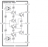
If You add cascode stage to the second stage too, the result will be even better (see the attached picture). You need to find transistors which are working well in the quasi saturation. This is the main reason of the low bias (1mA) in the input stage.
The collector current of the second stage would be double with ideal devices, but it is about 150-160% in the real life.
Sajti
Attachments
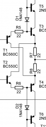
If You add cascode stage to the second stage too, the result will be even better (see the attached picture). You need to find transistors which are working well in the quasi saturation. This is the main reason of the low bias (1mA) in the input stage.
Sajti
You could sacrifice anotrher diode drop and use two diodes in series, that takes care of the very low Vce issue, no?
Jan
You could sacrifice anotrher diode drop and use two diodes in series, that takes care of the very low Vce issue, no?
Jan
I was thinking about it, but not with 2nd diode. I will try a single red LED. It will gives about 1,6V Vce...
Sajti
The Marantz circuit with the collectors returned to the emitters of the opposing level shifter does appear to mitigate the cut-off problem you have when the buffer collectors are returned to a high (10V in the nx and sx amplifiers) voltage. Per my earlier post, the solution in that variant is to increase the degeneration resistor values to develop a suitable stand-off voltage - in the nx and sx amplifiers the figure is 150mV. In the Marantz circuit, current is being supplied out of the level shifter emitter into the degeneration resistor and then the summing junction, and into the opposing buffer transistor collector. This appears to soften the sharp cut-off characteristic you have with the sx & nx front end when insufficient degeneration is provided. The current in the level shifter in the Marantz scheme is 1.5x to 2x that of the technique I use so you do need to scale either the level shifter collector load resistors or the degeneration resistors accordingly.
From simple sims, it appears this technique requires a bit more care in compensation. The bootstrapping action probably enhances the front end bandwidth (will need more investigation) - but that is neither here nor there in my book because for either variant it is many 10's of MHz.
The bootstrapping offered using this approach does indeed result in lower distortion (0.0009% vs 0.0011% in my simple model), again because of the bootstrapping action, provided the buffer transistors are well behaved in quasi saturation region.
I was thinking about it, but not with 2nd diode. I will try a single red LED. It will gives about 1,6V Vce...
Sajti
Looks good in the simulator. The amplifier gives 140W/8ohm, with 0.001% thd. Anyway no difference comparing to the single diode, but I don't know if the 550C/560C models are accurate with the quasy saturation.
Sajti
- Status
- Not open for further replies.
- Home
- Amplifiers
- Solid State
- Current feedback amplifier topologies and considerations