I use C1*L1=Z1*Z , It was my mistake because I didn't add ω.No it isn't. You gave C1*L1=Z1*Z. Where did you get that from?
This should not be a problem.
I want to understand why the current is not amplified by the transistor.Modified why?
It was your mistake because it didn't make sense.It was my mistake because I didn't add ω
Mistakes are always a problem.This should not be a problem.
It's all in the Walker-Albinson paper. Changing the circuit, wrongly, won't help you understand anything.I want to understand why the current is not amplified by the transistor
Ok,I'm very sorryIt was your mistake because it didn't make sense.
I tried to use the original circuit, but I have the same problem.It's all in the Walker-Albinson paper. Changing the circuit, wrongly, won't help you understand anything.
I want to understand why the current is not amplified by the transistor.
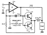
The voltage is amplified by OpAmp (B), current flows through the resistor R2\Rn (B-C-Ground). Transistors V1\V2 amplify the current that the load L1\Rn (D-C-Ground) receives. #18
Last edited:
But the current output by my transistor is several times smaller than the current of the resistor above.電壓經運算放大器放大,電流流經電阻。晶體管放大負載接收的電流。
An error current I2 flows through R2 (as long as V1\V2 are not turned on). After switching on, the main current I1 flows through L1 #18But the current output by my transistor is several times smaller than the current of the resistor above.
Last edited:
誤差電流流經R2(只要V1\V2不導通)。接通後,主電流流經L1
Is this the circuit diagram?
Attachments
You really have to give more info instead of just some words that don't mean a lot.But the current output by my transistor is several times smaller than the current of the resistor above.
Tell what you measured in the circuit, which circuit, why do you think it is wrong, what did you expect to measure?
Otherwise this can go on for a few more years with no progress.
Jan

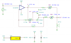
Ok,Below are the parts I put on according to the original circuit diagram.You really have to give more info instead of just some words that don't mean a lot.
Tell what you measured in the circuit, which circuit, why do you think it is wrong, what did you expect to measure?
Otherwise this can go on for a few more years with no progress.
Jan
My question is, I think that in the case of conduction, the current flowing out of the transistor should be larger than the above resistance, but as shown in the simulation diagram, the situation is not the same as I thought.
Attachments
You really don't get it, do you?
" I think that in the case of conduction, the current flowing out of the transistor should be larger than the above resistance, but as shown in the simulation diagram, the situation is not the same as I thought. "
What case of conduction? what current out of what transistor, what 'aboce resistor', what situation? I have no idea what you are talking about.
Good luck,
Jan
the current flowing out of the transistor should be larger than the above resistance
A current cannot be either larger than, equal to, or smaller than a resistance. You are talking nonsense. It is impossible to help you if you can't use standard terminology correctly.
Last edited:
A current cannot be either larger than, equal to, or smaller than a resistance. You are talking nonsense. It is impossible to help you if you can't use standard terminology correctly.
Hey , that's just my opinion,i didn't say that was right.You really don't get it, do you?
I'm just an amateur student.
I really don't understand the principle.
It's all explained in the Walker/Albinson paper. If you can't understand that, it's far too broad to be answered here.I really don't understand the principle.
The point is that your posts are so unclear that it's impossible to know what you mean or to answer!Hey , that's just my opinion,i didn't say that was right.
I'm just an amateur student.
I really don't understand the principle.
Has nothing to do with what you do or don't understand.
We're here to help people understand and progress, but you go a long way to make it impossible to get a meaningful discussion.
Please try to understand the point!
" I think that in the case of conduction, the current flowing out of the transistor should be larger than the above resistance, but as shown in the simulation diagram, the situation is not the same as I thought. "
What case of conduction? what current out of what transistor, what 'above resistor', what situation? I have no idea what you are talking about.
If you would say something like: "The Q2 collector current for the case that the dumpers are off would flow through L6 and generate a voltage between point A and B. How does that decrease the distortion?" we would have something to talk about.
Jan
Last edited:
https://en.wikipedia.org/wiki/Wheatstone_bridge
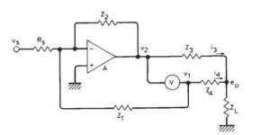
When the bridge circuit is well balanced, the output voltage should be equal to the voltage of the negative input of the amplifier. (refer to the original post)
For an ideal amplifier, the negative input pin should be equal to the positive input pin. If so, there will be no distortion.
When the bridge circuit is well balanced, the output voltage should be equal to the voltage of the negative input of the amplifier. (refer to the original post)
For an ideal amplifier, the negative input pin should be equal to the positive input pin. If so, there will be no distortion.
https://ru.wikipedia.org/wiki/Мост_Максвеллаbridge circuit
https://www.dadaelectronics.eu/uplo...nt-Dumping-explained-by-Peter-Walker-1975.pdf
The original current dumping concept from QUAD includes a very smart feedback network that changes it's feedback factor depending on whether the dumpers are on or not. It's a bridge type circuit with two arms formed by an inductor and a cap that have precise values.
https://www.diyaudio.com/community/threads/current-dumping-amplifier.243345/page-6
Last edited:
- Home
- Amplifiers
- Solid State
- Current dumping Maxwell bridge