Humm, I guess you are right 
Reflexions are still minimum phase, but they are not the original (EQed with a notch at Fs) signal but the one emitted by the cone (with a somewhat flat response at Fs), so I guess it can trigger the Fs resonance...?
Reflexions are still minimum phase, but they are not the original (EQed with a notch at Fs) signal but the one emitted by the cone (with a somewhat flat response at Fs), so I guess it can trigger the Fs resonance...?
Yes, that's how I see it too.It is better to have a well damped driver in the first place.........
......... why not just design the suspension for the intended use in the first place?
But then there is the argument that high mechanical resistance can be a source of non linearity...
MJR7-Mk5 Mosfet Power Amplifier Design Notes
I like the simplicity and well thought through design of this amp. It has some negative feedback, but i would not say "huge amount". Many modern amps has several extra gain stages just to maximize the open loop gain to "huge amounts". Add an LTP input stage, with cfp devices and current-mirrors and you could get 50 dB more gain and negative feedback. I don't think that would do much good for the stability of the amp.
See chapter "Gain Bandwidth product".
There is no secret behind the extremely low harmonic distortion products Mike Renardson obtained despite the not very linear Mosfet output stage.
This is where things get sticky. We are mixing electrically induced or controlled cone movement with sympathetic vibration of a mechanical device. You can not control the sympathetic vibration with the electrical signal, they are two distinct phenomena. While I do not think the amplifier will have any troubles in the least that does not mean that the speaker can not have a physical resonance that can be excited by a acoustical source. The example of one speaker working causing another to be excited is a perfect example of this, an amplifier connected to the second speaker has no effect on that mechanical coupling effect. This is what I was trying to say earlier in the conversation. If you send an electrical signal to a speaker driving it a certain frequencies the harmonics of that signal can indeed excite the speaker at other frequencies that the mechanical system is sensitive to, I see no way that any passive or active EQ can address that physical phenomena? This is why you want to look for real mechanical resonances in a device when you are designing it in the first place, if the device has those mechanical resonance anything producing sound at those frequencies will excite that mechanical resonance, it is a mechanical problem and has nothing to do with the electrical side of things. You can not electrically stop this, not even with deep notch filters at that mechanical frequency since the excitation is not electrically stimulated.
Now this has nothing to do with feedback or FR response correction on the electrical side. A high Q electrical response aberration in FR can easily as has been shown be corrected. If it is simply the frequency response peaks and dips we can correct that, these are distinct problems from the mechanical problems that can occur in a real driver.
Let's just say that in a dome tweeter we can cut some resonant frequency that is making the dome go into a breakup mode. But there is no way to electronically change where physically that cone would bend at a specific frequency from that frequency, the Eigen modes are unaffected by an electrical signal, The physical properties of the diaphragm material are not changed by electrical signal, two phenomena that are have no correlation.
Someone can rip me a new one, I am open for a serious answer on where I am misunderstanding the difference between physical phenomena and electrical signal interaction.
When it's provided by an elastomer that may be true in principle, but much depends on how 'high' is high I suppose. Similar discussion arises in phono cartridges, where both damping and spring is provided by one elastomer. In practice, there's nothing to divide cartridge suspensions having Q ranging from about 2 thru 12 in terms of distortion in that case.But then there is the argument that high mechanical resistance can be a source of non linearity...
But then there is the argument that high mechanical resistance can be a source of non linearity
I would argue that it is mainly the demand for high xmax that is the primary source of non-linearity in the suspension of a low Qms high Rms driver. It is much easier to maintain a high level of linearity with only 3 mm xmax. I prefer large radiating surface to large xmax anyway, and especially so with high efficiency drivers.
There is no secret behind the extremely low harmonic distortion products
No of course there it is no secret. Cascoding a gain stage makes it much more linear without any extra feedback or open loop gain. It is a simple circuit with fewer non-linear devices in series, lowering the need for extreme amounts of feedback to linearise them. A few inherent linear gain stages does not need as much feedback as several high gain less linear gain-stages would need.
http://www.firstwatt.com/pdf/art_cas_amp.pdf
I admire people that can squeeze more performance from very simple circuits then the no-brain usual approach of adding gain to maximize feedback without any thought of finesse, elegance or economy of parts.
Cascoding a gain stage makes it much more linear without any extra feedback or open loop gain.
Per se, not really. Sometimes even the contrary.
Cascoding provides a very high impedance to the output of a device.
Loading this output with a high impedance source, i.e. a constant current source, and adequately buffering it, leads to a very high forward voltage gain.
Well managed, this allows high values of negative feedback from beautifully simple stages.
This was perfectly exploited Linsley-Hood in 1978. Cascoding the BC184C of this inverting circuit led to a very low distortion, it was called "Super-Liniac" by its author.
http://www.diyaudio.com/forums/analogue-source/267770-jlh-liniac-riaa.html#post4180709
See also pages #94, #100 and #101 of the book indicated below.
The real reasons of the good linearity of the above circuit when using a cascode are given.
https://books.google.fr/books?id=Sv...epage&q=per art of linear electronics&f=false
.
Thanks Forr for the links.
You are right. I use cascode mainly to lower voltage variations through the the device to lower the influence of Ciss on the bandwith and to linearize the device, but cascode can be used for very high voltage gain. I had not realized this, since i mainly build very simple low open gain - low (or no global feedback) feedback amps.
Even with a voltage-gain of 1000 i would not say "high gain", but rather "normal gain to slightly less the normal" for a class A/B amp, and especially so for a mosfet output stage.
Cheers,
Johannes
Today i modified my latest 3 watt Triadtron to have an very high out-z. I did not measure it but i guess it is 500 ohm or so (i have a 1 kohm resistor from output to ground to bleed of any voltage from the output capacitor). I tested to drive my MLTL (Beyma 12P80Nd) from one channel of my QSC RMX1450 with 470 ohm resistor in series, and it sounded very similar. It had the same elevated response around Fs and in the treble. My Triadtron was much louder and had a much more lively and smooth silky midrange (vocals and piano).
It is not difficult to have an extremely high output impedans. I don't have any global feeback and very little voltage gain to begin with. No problem driving anything from a dead short to parallel resonant circuits, loudspeakers and LEDs pulsing with the music.
It is fun playing with current drive and hearing the results.
Cheers,
Johannes
Today i modified my latest 3 watt Triadtron to have an very high out-z. I did not measure it but i guess it is 500 ohm or so ...
Hi
Please show the schematic, if it is not a secret🙂
No schematic right now. It is a work in progress and i am constantly changing things and testing new ideas.
There is a lot of information about the Triadtron on Tube CAD Journal It is the inverted Triadtron with voltage gain i am using as a base for my experiments.
Cheers,
Johannes
There is a lot of information about the Triadtron on Tube CAD Journal It is the inverted Triadtron with voltage gain i am using as a base for my experiments.
Cheers,
Johannes
What program are you using for those nice schematics Pawel?
I have no experience of Spice (drug or electronic simulation). I have tried once many years ago, but all the "experience" i got was a feeling of absolute helplessness and despair..
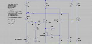
The "Triadtron" is a really nice circuit in real life too. I have built a few and they work admirably. Stable. Low distortion (only by ears).
This is the inverted Triadtron. Q1 is a IRFP150 with the drain instead of the source attached to the output.
Cheers,
Johannes
I have no experience of Spice (drug or electronic simulation). I have tried once many years ago, but all the "experience" i got was a feeling of absolute helplessness and despair..
The "Triadtron" is a really nice circuit in real life too. I have built a few and they work admirably. Stable. Low distortion (only by ears).
This is the inverted Triadtron. Q1 is a IRFP150 with the drain instead of the source attached to the output.
Cheers,
Johannes

This is the basic idea. It is a work in progress.
The resistors forming the bootstrap is 470 ohms each.
Cheers,
Johannes
ltspice
LTSpice from LT http://ltspice.linear-tech.com/software/LTspiceIV.exe
free and realy fine, the learning will take you not so long, Mooly created fine thread in "Software tools" @ diyaudio: http://www.diyaudio.com/forums/software-tools/260627-installing-using-ltspice-beginner-advanced.html
What program are you using for those nice schematics Pawel?
LTSpice from LT http://ltspice.linear-tech.com/software/LTspiceIV.exe
free and realy fine, the learning will take you not so long, Mooly created fine thread in "Software tools" @ diyaudio: http://www.diyaudio.com/forums/software-tools/260627-installing-using-ltspice-beginner-advanced.html
Thanks!!
I will try to learn this program. I think that was the program i tested back in 2004, but failed utterly to understand.
Cheers,
Johannes
I will try to learn this program. I think that was the program i tested back in 2004, but failed utterly to understand.
Cheers,
Johannes
for playing
Hi Johannes
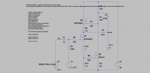
Attached you will find asc file with your amp for playing with,
it contain the models and should work just after installing LTSpice.
have fun!
Hi Johannes
Attached you will find asc file with your amp for playing with,
it contain the models and should work just after installing LTSpice.
have fun!
Attachments
Thanks Pawel!!
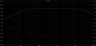
I have just made my first 2 DC simulations in LT-Spice.
I will try this file, once I understand what I am actually looking at.
regards,
Johannes
I have just made my first 2 DC simulations in LT-Spice.
I will try this file, once I understand what I am actually looking at.
regards,
Johannes
- Home
- Amplifiers
- Solid State
- Current drive for Loudspeakers