Didn't realize it was called the Mullard flash! My flashy 12AX7 is, in fact, a Mullard tube.
The resistance change might be somewhat of a positive feedback but I feel it is being a bit exaggerated here. Power = I^2 R. Current being constant means that the heater power is directly proportional to the heater resistance.
Resistance change in a heater is fairly linear from ~2 ohms at 20C to 21 ohms at, lets say, 900C, middle of the road for a small signal tube. That's a change of ~0.0216 ohms per degree C.
There just isn't enough resistance change to cause a runaway.
i) To raise the cathode at 1100°K the heater must be at about 1600°K
ii) A heater fed by constant current does not exhibit "Mullard Flash" due to inherent soft start.
iii) At these temperatures, resistivity and hence resistance is not a linear function of absolute temperature.
iv) It is not clear to me why there just isn't enough resistance change to cause a runaway. Could you please post a more detailed calculation?
Assuming that the temperature difference between heater and ambient is proportional to power and that the resistance has a first-order relation with temperature (second- and higher-order temperature coefficients neglected), you can calculate the loop gain from those figures:
Suppose the temperature difference increases by 1 % for some reason. That's 8.8 K more temperature, so resistance increases by 0.19 ohm. The resulting increase in power under constant current drive is (0.19 ohm/21 ohm) * 100 % ~= 0.9047619 %.
Hence, the loop gain estimate is 0.9047619. That's less than 1, so you get no thermal runaway, but it does amplify inaccuracies by a factor of 1/(1 - 0.9047619) ~= 10.5.
i) For small temperature changes, resistivity can be approximated by
ρ = ρo (1 + α (T - To))
I have no idea how good it is that approximation for tungsten at 1600°K
ii) It is difficult to find your loop gain estimate, e.g. you must also consider the Stefan-Boltzmann law
ℇ = σ T⁴
Modified in the form
E = Co (T⁴ - To⁴)
Neglecting the heat transported to the exterior of the valve by conduction on the connection wires you can assume that all the heat is evacuated by radiation, now you can compare this heat with the heat absorved by the heater and obtain your estimate.
It would be fairly easy for someone to measure the heater current and voltage for a typical audio valve in the region of the normal power, and see how they vary. May be better than speculation or linear interpolations?
12AY7 Heater Measurements,,,,
V,I(A),R,P(W),
10.0,0.129,77.5,1.3,
10.5,0.131,80.2,1.4,
11.0,0.135,81.5,1.5,
11.5,0.138,83.3,1.6,
12.0,0.141,85.1,1.7,
12.5,0.145,86.2,1.8,
12.6,0.150,84.0,1.9,Datasheet Spec
13.0,0.149,87.2,1.9,
13.5,0.151,89.4,2.0,
14.0,0.155,90.3,2.2,
14.5,0.158,91.8,2.3,
15.0,0.161,93.2,2.4,
15.5,0.165,93.9,2.6,
16.0,0.169,94.7,2.7,
Comma delimited for someone wanting to play with the numbers I guess.
From 10V to 16V in 0.5V steps. I don't have an easy or quick way to measure temperature. That would require me to fire up the high vacuum chamber with a broken tube that I've attached thermocouples to, but it could be done...
Comparing the measurements at 12 V and at 13.5 V, a voltage increase of 12.5 % corresponds to a current increase of 7.092199 %. This already shows that with current drive, the current needs to be regulated more accurately than the voltage with voltage drive, although not nearly as dramatically as I calculated earlier.
Under current drive, 1 % resistance increase causes 1 % of power increase, under voltage drive (using a first-order Taylor approximation) 1 % resistance increase causes 1 % of power decrease. That is, the magnitudes of the loop gains are the same under voltage and current drives, but the signs are opposite.
Positive feedback with a loop gain of A*beta increases whatever disturbance there may be by a factor of 1/(1-A*beta), while negative feedback with a loop gain of -A*beta decreases it by a factor of 1/(1+A*beta).
Under voltage drive, a change of the heater voltage of 12.5 % has the same impact as a change of the heater current of 7.092199 % under current drive (*). Hence, (1+A*beta)/(1-A*beta) ~= 12.5 %/7.092199 %, so A*beta ~= 0.2760181.
This is almost a factor of four lower than what I calculated earlier. It would theoretically have been exactly a factor of four if all heat were dissipated by radiation and if the heater's resistance had only a first-order temperature dependence.
(*): I'm applying the substitution theorem here, which implies that I assume that each voltage corresponds to one and only one current and vice versa.
Last edited:
LOL. Amusing thread.
DF96 had a point that stands repeating. Namely that tubes not specifically 300 mA series-string designed are better fed a constant voltage, as the manufacturers have (and take) liberties in designing their filament current demands to achieve a particular heater temperature.
Except for magnetic phono pickups (and ribbon-type microphones) where the voltages involved are sooooo miniscule, having special DC heaters seems unwarranted for most indirect heated vacuum tubes. If its a "6" tube, feed its heaters 6.3 VAC. If its a "12" tube, then either 6-0-6 (as most have center taps) or just 12.6 VAC. Tightly twist those heater power will keep 'em away from the signal line path.
If I'm dealing with sensitive front ends (per above), then I go with regulated DC heaters for that stage and the one(s) following. Might as well. I like the robustness of top-shelf manufacturer linear voltage regulators, as they're "solder-and-forget" devices.
Just saying,
GoatGuy
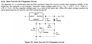
If you are worried about heater surge at power-up, and don't want to fool with the inaccuracy of constant current, why not spend another nickle on an additional transistor, and use this handy scheme from the datasheet for the LM317-

Of course you will need to select the right resistors for the desired output voltage, but this particular circuit works well. If you need more current, use an additional pass transistor or a bigger IC like the LM338. Use plenty of heatsink, of course. I've used this for supplying power hungry filaments on sweep tubes in the past and it works very well. This gives you a slower warmup time (increase the cap to increase the time it takes to come up) and a steady DC voltage across the filaments. Easy peasy.
Cheap, easy, effective. 😎
Attachments
I suppose this should have been asked earlier but what disturbances are we talking about? There isn't a lot that can happen to a heater. It goes open, shorts, or works. Only an inter-heater short would cause a change and in CV it's an increase in heat and in CC a lowering of it.
This 3A5 sheet has info on using a shunting resistor when operating in series. http://www.tubebooks.org/tubedata/HB-3/Receiving-Type_Industrial_Tubes/3A5.PDF
12AY7 Heater Measurements,,,,
V,I(A),R,P(W),
10.0,0.129,77.5,1.3,
10.5,0.131,80.2,1.4,
11.0,0.135,81.5,1.5,
11.5,0.138,83.3,1.6,
12.0,0.141,85.1,1.7,
12.5,0.145,86.2,1.8,
12.6,0.150,84.0,1.9,Datasheet Spec
13.0,0.149,87.2,1.9,
13.5,0.151,89.4,2.0,
14.0,0.155,90.3,2.2,
14.5,0.158,91.8,2.3,
15.0,0.161,93.2,2.4,
15.5,0.165,93.9,2.6,
16.0,0.169,94.7,2.7,
Comma delimited for someone wanting to play with the numbers I guess.
From 10V to 16V in 0.5V steps. I don't have an easy or quick way to measure temperature. That would require me to fire up the high vacuum chamber with a broken tube that I've attached thermocouples to, but it could be done...
Comparing the measurements at 12 V and at 13.5 V, a voltage increase of 12.5 % corresponds to a current increase of 7.092199 %. This already shows that with current drive, the current needs to be regulated more accurately than the voltage with voltage drive, although not nearly as dramatically as I calculated earlier.
Under current drive, 1 % resistance increase causes 1 % of power increase, under voltage drive (using a first-order Taylor approximation) 1 % resistance increase causes 1 % of power decrease. That is, the magnitudes of the loop gains are the same under voltage and current drives, but the signs are opposite.
Positive feedback with a loop gain of A*beta increases whatever disturbance there may be by a factor of 1/(1-A*beta), while negative feedback with a loop gain of -A*beta decreases it by a factor of 1/(1+A*beta).
Under voltage drive, a change of the heater voltage of 12.5 % has the same impact as a change of the heater current of 7.092199 % under current drive (*). Hence, (1+A*beta)/(1-A*beta) ~= 12.5 %/7.092199 %, so A*beta ~= 0.2760181.
This is almost a factor of four lower than what I calculated earlier. It would theoretically have been exactly a factor of four if all heat were dissipated by radiation and if the heater's resistance had only a first-order temperature dependence.
(*): I'm applying the substitution theorem here, which implies that I assume that each voltage corresponds to one and only one current and vice versa.
And thermal runaway??? 😕
Data from a heater perfectly on specs tells nothing about runaway. 🙄
Data from a heater perfectly on specs tells nothing about runaway. 🙄
Again, what failure mode are we looking at that you expect that to happen with CC vs CV?
And thermal runaway??? 😕
Data from a heater perfectly on specs tells nothing about runaway. 🙄
What the hell do you mean by thermal runaway then?
All cases of thermal runaway I'm familiar with are basically positive feedback mechanisms: something that gets hot starts drawing more power, gets even hotter and so on, and as the loop gain of this positive feedback mechanism is greater than or equal to 1, things get out of hand. That has absolutely nothing to do with being on or off spec.
If you are worried about heater surge at power-up, and don't want to fool with the inaccuracy of constant current, why not spend another nickle on an additional transistor, and use this handy scheme from the datasheet for the LM317-
Yes, that should do the trick if you make the time constant long enough. An NTC meant for inrush current limiting also works fine. You loose half a volt or so because resistance doesn't go to zero after heating up, but that's it.
Last edited:
I suppose this should have been asked earlier but what disturbances are we talking about? There isn't a lot that can happen to a heater. It goes open, shorts, or works. Only an inter-heater short would cause a change and in CV it's an increase in heat and in CC a lowering of it.
The disturbances I write about are voltage or current tolerances, valve tolerances, changes in ambient temperature and so on.
The power:
V^2/R and I^2*R
If R increases with temperature, when V is stabilized power decreases with temperature. If I is stabilized, power increases with temperature. That means, when voltage is stabilized, the filament itself regulates own temperature, when current is stabilized, the temperature increase increases power increasing temperature. Popilin is right, it is similar to run-away.
When I designed a tool to calibrate IR temperature sensor, I used negative output resistance to power an incandescent lamp. It worked pretty well. Probably, the best way would be to use speed regulators from cassette tape motors. 🙂
Last edited:
1 + 0.276 + 0.276^2 + 0.276^3 + ... = 1/(1-0.276) ~= 1.38. Doesn't tend to infinity, does it?
Last edited:
Again, what failure mode are we looking at that you expect that to happen with CC vs CV?
You still owe to me an answer from here
https://www.diyaudio.com/forums/tubes-valves/331270-current-drive-6922-filaments-9.html#post5638805
What the hell do you mean by thermal runaway then?
All cases of thermal runaway I'm familiar with are basically positive feedback mechanisms: something that gets hot starts drawing more power, gets even hotter and so on, and as the loop gain of this positive feedback mechanism is greater than or equal to 1, things get out of hand. That has absolutely nothing to do with being on or off spec.
As valves that we often use do not need heat sinks, heater thermal runaway must be a consequence of a defect, Morgan Jones say that he have had two heater failures in thirty years, and just one by thermal runaway.
The process needs a positive feedback mechanism as you pointed up, but it also needs an initial condition like a hot spot, then, a valve perfectly on specs is unlikely to suffer thermal runaway.
I would like to see some detailed calculations on the subject, but I am losing that hope.
The power:
V^2/R
and I^2*R
If R increases with temperature, when V is stabilized power decreases with temperature. If I is stabilized, power increases with temperature.
That means, when voltage is stabilized, the filament itself regulates own temperature, when current is stabilized, the temperature increase increases power increasing temperature. Popilin is right, it is similar to run-away.
When I designed a tool to calibrate IR temperature sensor, I used negative output resistance to power an incandescent lamp. It worked pretty well.
Probably, the best way would be to use speed regulators from cassette tape motors. 🙂
Hi Anatoliy! Good to see you around here!
I did a similar reasoning here
https://www.diyaudio.com/forums/tubes-valves/331270-current-drive-6922-filaments-6.html#post5637399
But some folks do not want that, maybe they hear you with more interest.
Пока!
As valves that we often use do not need heat sinks, heater thermal runaway must be a consequence of a defect, Morgan Jones say that he have had two heater failures in thirty years, and just one by thermal runaway.
Does that mean that we finally agree that healthy valves work fine with current- as well as with voltage-driven heaters, even though heating with voltage is inherently more accurate? That would be a breakthrough!
The process needs a positive feedback mechanism as you pointed up, but it also needs an initial condition like a hot spot, then, a valve perfectly on specs is unlikely to suffer thermal runaway.
If you are thinking about a part of the heater being hotter than the rest and eventually getting too hot: if the loop gain of the positive feedback is greater than one, the slightest imbalance would grow exponentially until destruction. With initial temperature differences of 0.000001 K it would take ln(1/0.000001) ~= 13.8 time constants longer for the heater to self-destruct than with initial temperature differences of 1 K, but that's all.
So far I was under the impression you were thinking about an entire current-driven heater being hotter than intended, getting hotter again due to positive feedback and eventually self-destructing. If the loop gain of that mechanism were greater than one and you would aim for the nominal current, you would have 50 % chance of the heater becoming much too hot and 50 % chance of it staying much too cold.
I would like to see some detailed calculations on the subject, but I am losing that hope.
No need to lose hope, just do whatever calculation you want done yourself and post the results.
Hi Anatoliy! Good to see you around here!
I did a similar reasoning here
https://www.diyaudio.com/forums/tubes-valves/331270-current-drive-6922-filaments-6.html#post5637399
But some folks do not want that, maybe they hear you with more interest.
Пока!
I wrote the exact same in post 2 of this thread, no idea why it has to be repeated all the time.
So the conclusion is:
1. current drive is unnecessary, but does no harm
2. voltage drive does not need to be particularly accurate
3. if using voltage drive, be aware of 'cold' current surge - this often catches out newbies, who use a 1A regulator to drive three heaters (0.9A) and then wonder why the regulator shuts down every time they switch on
4. for most purposes unregulated AC is fine
- Home
- Amplifiers
- Tubes / Valves
- Current drive for 6922 filaments