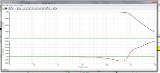
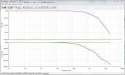
Look at a transient response perhaps. The rising phase response is weird, I think it should continue falling (going negative), not climbing -- that would seem to indicate non-causal behavior. Bode plot doesn't always show stability.
A 8Mhz audio op-amp, even if it is unity gain stable, can't have enough phase margin with such a lag as the load (each transistor stage contributes >90 deg lag at some point at HF).
A simple solution for servos and the like is to add a capacitor across input terminals of op-amp (requires a series resistor at one end). Other frequency compensation solutions involve: taking split feedback before and after output stage, or compensating output stage in such a way that phase margin is 45 deg at the frequency where circuit runs out of open-loop gain.
Such circuits where op-amps and transistors are mixed shall be tested in breadboard for transient response at low and high temperature (heat gun or box/light bulb and IR thermometer), to ensure reliability.
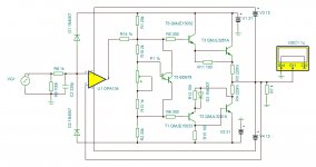
Another current booster with op amp.
Bridged Buffered Opamp Amp - a journey
A completed project.
I works, it has low parts and excellent quality.
Bridged Buffered Opamp Amp - a journey
A completed project.
I works, it has low parts and excellent quality.
Last edited:
There is also another problem. The OPamp power supply should always be more than half of the output stage power supply voltage, or the inputs of the OPamp can end up being driven outside their common mode range (i.e. too close to the OPamp power supply rails) which can have various detrimental effects depending on the OPamp used. Usually the OPamp OLG becomes non-linear and degrades close to at least one rail, and in some cases worse things such as phase reversal and latch-up can happen. With OPamps prone to that kind of behavior, feeding an input signal with a too high rise or fall time, or too high a frequency, or just driving the circuit to clipping, can cause overshoot and oscillation which will repeatedly drive the OPamp input stage into modes of operation it cannot stand, leading to serious problems and potential circuit destruction.
Where this "more than half of the output stage power supply voltage" comes from ?The OPamp power supply should always be more than half of the output stage power supply voltage, or the inputs of the OPamp can end up being driven outside their common mode.
Not all op amps are the same, some are rail to rail some are latch up free, some don' t.
Obviously, for this design this should be considered.
Another current booster with op amp.
Bridged Buffered Opamp Amp - a journey
A completed project.
I works, it has low parts and excellent quality.
Thanks, but it is not unity-gain.
you could drive a 1 ohm load with that. BJT transistors are too slow for 9 mhz or higher unity gain stability. if you are driving the grids the op amp alone provides 100x the required current.
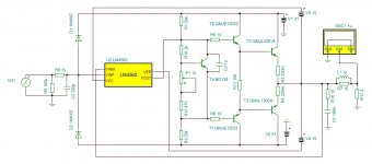
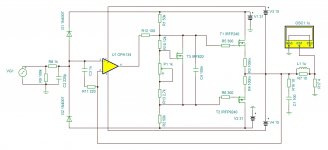
I have changed opamp to LM4562 - 55 Mhz bandwidth and unity-gain stable.
Still I don´t know how to compensate the circuit.
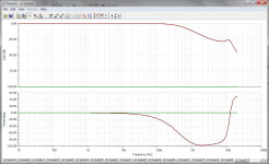
The important point is improving the speed of the buffer, not the opamp. Having a 55 MHz GBW makes this problem worse than the 8 MHz of the original circuit, instead you need to focus on improving the speed of the output stage and figuring out how to let it peacefully cross the unity gain frequency.
This dual PSU is strange. The output voltage fed back at the op amp can overdrive the op amp input voltage. I see clamping diodes but not at the right place to prevent this over ride.
What about this?
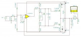
I have changed output transistors to mosfets, back to OPA134 and added opamp compensation. Is it worth building the prototype for testing?
I have changed output transistors to mosfets, back to OPA134 and added opamp compensation. Is it worth building the prototype for testing?
Attachments
Last edited:
The OPA134 with +/-15V supplies can only swing 14V peak.
The output is <unity gain so won't swing even 14V.
Why are you feeding over twice that power voltage to the outputs?
The output is <unity gain so won't swing even 14V.
Why are you feeding over twice that power voltage to the outputs?
I overlooked the op amp supply bootstrapping.OPA134 power supply is bootstrapped from the output so it can swing higher than +/- 15V. I updated the schematic.
It has some popularity and pops up regularly. I doubt this realy works.

Last edited:
D1 and D2 aren't needed, its unlikely that you will get +/-31 volts on the input.
Not convinced about Vbe multiplier.
They usually have a constant current source to keep voltage stable.
If current reduces through multiplier you will get higher bias voltage.
But I could be wrong....
Not convinced about Vbe multiplier.
They usually have a constant current source to keep voltage stable.
If current reduces through multiplier you will get higher bias voltage.
But I could be wrong....
Hello, why not a circuit like this ? (Without transforma)
http://www.diyaudio.com/forums/solid-state/10053-minimalist-fet-amplifier.html#post115106
http://www.diyaudio.com/forums/solid-state/10053-minimalist-fet-amplifier.html#post115106
- Status
- Not open for further replies.
- Home
- Amplifiers
- Solid State
- Current boosted unity-gain opamp