Wow that’s a really good picture. I’ve never Seen these with provided dimensions like thatBooger weldz: I loosely based the baffle to front opening angle on the picture below. Having the port enter at the other end of the Karlson slot will likely have worse low end performance. The extra space due to the angling won't increase performance for the infra part, that's for sure. How would you go about it?

Freddi: So was I, wouldn't mind a collab to make this work though.
I uploaded it many years ago - its from the January 1954 issue of Radio and Television News magazine (which also featured a Theremin by Robert Moog)
Karlson did the same with the July 1958 issue of Popular Mechanics magazine for his 12 inch cabinet ( -that was the second version)
Those gvieaways resulted in a flurry of DIY builds with some surviving to this day.
Karlson did the same with the July 1958 issue of Popular Mechanics magazine for his 12 inch cabinet ( -that was the second version)
Those gvieaways resulted in a flurry of DIY builds with some surviving to this day.
I think an infra sub is mostly for fun, if that's not your thing just move on 😉
Simply listening to some YT videos where people didn't high pass their microphones makes it sometimes sound like my neighbors are breaking down their house on my regular 30 Hz+ subs. Also when doing parties, anything under 40 Hz gave some serious turntable feedback issues, whilst most rock and live music seemed to stop under 40 - 50 Hz anyway. High passing helps, having a musical sub taking it over at 30 - 60 Hz helps. However if I want to impress my guests or need a grin on my face I turn on my infra sub without a high pass.
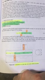
In short, that particle velocity is probably misleading, you're not interested in the port velocity at either the throat or mouth as long as it's not cause for concern. You're interested in the port velocity at the smallest port/ horn area that is within hearing range (in this case at S3). which by the way seems to be rather small. As a rough estimate I would use 20" x 1 3/16" x (2.54)^2
By adding up the panel lengths along the path of the port I get 158 cm (62") port length, up to the baffle entrance (so without the front chamber). I think you can also add another 3 x 1 3/16" corners and 3 x 3/4" panel thickness to that.
In my experience the HR sim shows exaggerated peaks and dips that are not present in any tapped horn measurements I've seen on the web. Does that also mean that impulse response is better than simulated? Secondly, using a low pass filter will smooth the upper response, is it better to simulate impulse response after applying a LP filter in the filter wizard?
Simply listening to some YT videos where people didn't high pass their microphones makes it sometimes sound like my neighbors are breaking down their house on my regular 30 Hz+ subs. Also when doing parties, anything under 40 Hz gave some serious turntable feedback issues, whilst most rock and live music seemed to stop under 40 - 50 Hz anyway. High passing helps, having a musical sub taking it over at 30 - 60 Hz helps. However if I want to impress my guests or need a grin on my face I turn on my infra sub without a high pass.
I do get funny "crazy low" numbers on particle velocity
In short, that particle velocity is probably misleading, you're not interested in the port velocity at either the throat or mouth as long as it's not cause for concern. You're interested in the port velocity at the smallest port/ horn area that is within hearing range (in this case at S3). which by the way seems to be rather small. As a rough estimate I would use 20" x 1 3/16" x (2.54)^2
By adding up the panel lengths along the path of the port I get 158 cm (62") port length, up to the baffle entrance (so without the front chamber). I think you can also add another 3 x 1 3/16" corners and 3 x 3/4" panel thickness to that.
In my experience the HR sim shows exaggerated peaks and dips that are not present in any tapped horn measurements I've seen on the web. Does that also mean that impulse response is better than simulated? Secondly, using a low pass filter will smooth the upper response, is it better to simulate impulse response after applying a LP filter in the filter wizard?
I don't recall seeing a Hornresp impulse response simulation.In my experience the HR sim shows exaggerated peaks and dips that are not present in any tapped horn measurements I've seen on the web. Does that also mean that impulse response is better than simulated?
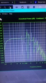
Looks like impulse response is tightest on sealed, more spread on ported, and further spread on tapped horns (from Josh Ricci's Data Bass):

The group delay sims are similar to actual measurements, and adding filters increases group delay in both.Secondly, using a low pass filter will smooth the upper response, is it better to simulate impulse response after applying a LP filter in the filter wizard?
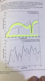
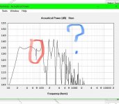
Going back to the exaggerated peaks and dips that are not present in actual measurements, David now has Vented-box enclosure system losses taken into account using the QL quality factor parameter. If the Loudspeaker Wizard slider is set to the maximum position, the true lossless model is selected.
Without the QL parameter the output of the port will appear more peaky and greater than it will when actually measured.
I'd expect that if a similar QL parameter could be included in TH models, the response would conform to measured results more closely.
Which brings up another difficulty- Hornresp (and pretty much any simulation program) won't accurately predict the Fb of a vented system if one simply uses port area and length if the port is not a standard round tube/pipe well away from all interior surfaces.
What is the Fb (impedance/excursion minima) of the Cubo Infra?
Art
I do 😉I don't recall seeing a Hornresp impulse response simulation
The group delay sims are similar to actual measurements, Going back to the exaggerated peaks and dips that are not present in actual measurements
That is good to know but not the point I was making. As we're dealing with exaggerated peaks and dips in the frequency response (outside of the usable bandwidth), simulating a low pass filter before calculating the impulse response, greatly cleans up/ softens the calculated response. So my question is which of these two (standard impulse response vs low passed impulse response) is closer to the measured impulse response?
Regarding the other question, I'll send you a PM..
The answer would depend on the filter set used in the measured impulse response 😉As we're dealing with exaggerated peaks and dips in the frequency response (outside of the usable bandwidth), simulating a low pass filter before calculating the impulse response, greatly cleans up/ softens the calculated response. So my question is which of these two (standard impulse response vs low passed impulse response) is closer to the measured impulse response?
Regarding the other question, I'll send you a PM..
Regardless of filters used (IIR or FIR) even with the "masked" option, the Hornresp simulatedport peaks and dips will be higher than measured.
Oh well, nothing's perfect..

SBB4 is said to have the best transient response of standard bass reflex alignments. Those embedded notes are from the late DJK.
Attachments

Last edited:
I've made cubo mod 3 years ago and was happy with the results. Will try INFRA too, looks interesting enough and simple to build.I think an infra sub is mostly for fun, if that's not your thing just move on 😉
Simply listening to some YT videos where people didn't high pass their microphones makes it sometimes sound like my neighbors are breaking down their house on my regular 30 Hz+ subs. Also when doing parties, anything under 40 Hz gave some serious turntable feedback issues, whilst most rock and live music seemed to stop under 40 - 50 Hz anyway. High passing helps, having a musical sub taking it over at 30 - 60 Hz helps. However if I want to impress my guests or need a grin on my face I turn on my infra sub without a high pass.
In short, that particle velocity is probably misleading, you're not interested in the port velocity at either the throat or mouth as long as it's not cause for concern. You're interested in the port velocity at the smallest port/ horn area that is within hearing range (in this case at S3). which by the way seems to be rather small. As a rough estimate I would use 20" x 1 3/16" x (2.54)^2
By adding up the panel lengths along the path of the port I get 158 cm (62") port length, up to the baffle entrance (so without the front chamber). I think you can also add another 3 x 1 3/16" corners and 3 x 3/4" panel thickness to that.
In my experience the HR sim shows exaggerated peaks and dips that are not present in any tapped horn measurements I've seen on the web. Does that also mean that impulse response is better than simulated? Secondly, using a low pass filter will smooth the upper response, is it better to simulate impulse response after applying a LP filter in the filter wizard?
Me neither, but using the HELP file's 'Find' option, found it 'buried' in the Filter Wizard, though only when opened in HR, not when in the Loudspeaker Wizard. 🙁I don't recall seeing a Hornresp impulse response simulation.
So how would this compare to a lab12c in a similar size vented box tuned to 20 hz? From freddi's model the cubo picks up a few db in the upper bass. Would port compression be low with the cubo?
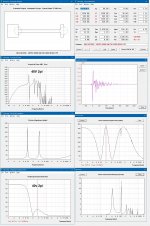
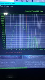
What does the raw response of this creation look like, without the LP filtering?
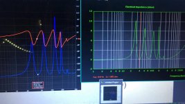
What about the measured impedance curve? I'm curious as to where the actual resonance frequencies turned out to be.
Looking back at post #5, I'm not sure that you really answered my question about how does the response compare to that of the driver mounted in a vented box of the same volume.
And as for the concerns about impulse response, well, duh, it's a subwoofer, producing frequencies with wavelengths over a meter. Should we care? 🙂
This is key and should be everyone’s number one rule especially when lining up a quarter wave resonators in series or parallel in higher ordersNope, just as long as it produces distortion free BASS!
The elephant in the room is the use of offset driver entry point (any driver entry point should be an odd harmonic interval which can be found and used and also is to lambda divided by four )has both a timing element or synchronicity to begin with and to finish with and to distance between drivers with all at the same time but also the fact that the pressure at that location is key to operating a thermal acoustic motor in the same exact way we find an awesome driver entry transmission line or any harmonic that useful that fits in the system as well
we all understand the 3×1/4 harmonic and what that does in a transmission line of 300 cm long if you are looking at the 100 cm as 86.4 you get approximately 104.72 in the location as to where that is within correction but at the same exact time we forget in a higher order enclosures for use of offset driver on both sides of the cone which is an absolute beautiful thing because it’s like adding higher orders to the enclosure or distributing more locations of resonators essentially along the way because it does in fact flatten the response even further and in more than one location as a result of parallel transmission linesAnd things that Paraflex could have been if only it had looked at these details from the start
We don’t even have to be mathematicians we can just draw things to scale centimeters is a millimeter or even 1,000,000 km if need be
Attachments

Last edited:
hereI do not want that in higher orders because it is a disaster and the warning is that sketch mark of misalignment alreadyIn the simulation tool to observe and get rid of in the higher order enclosures or pay the price and have to listen to what that causes(it sucks!!!)
Attachments
so line it up perfectly and even if your driver doesn’t give you the best response that’s too bad this is how things work
Attachments

- Home
- Loudspeakers
- Subwoofers
- Cubo Infra