hi,
I am working on the above mentioned amplifier. it is going into protect and i feel it is due to DC on the speaker terminals. Anybody have schematic for the same or help me in forcing the amp to come on to enable me check the voltages. Thank you,
Imran
I am working on the above mentioned amplifier. it is going into protect and i feel it is due to DC on the speaker terminals. Anybody have schematic for the same or help me in forcing the amp to come on to enable me check the voltages. Thank you,
Imran
I have changed main output driver IC and LM211 and still have no oscillations. No audio. Can anybody throw some light on this. Thank you.
Post photos if no one can answer your questions. I have no clue what this amp is.
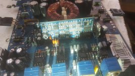
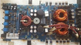
Here are the picture of driver board and main board. Thank you.
Attachments
If you solder a bridge between pins 2 and 3 of the 21844, does the amp power up with no DC on the output filter inductor?
If you solder a bridge between pins 2 and 3 of the 21844, does the amp power up with no DC on the output filter inductor?
yes there is no DC on filter inductor when pin 2 and 3 are bridged, probes placed on secondary ground and inductor.
If you drive a strong signal into the amp, do you see drive pulses on pin 1 of the driver IC?
without removing the bridge between pin 2 and pin 3 i drove 100hz signal and i got oscillations on pin 1 and i am attaching the same here for your reference. Thank you.
Attachments

Is that waveform driving precisely back down to the negative rail?
Was the problem precisely the same before replacing the ICs on that board as it is now (without the 2-3 jumper)?
Was the problem precisely the same before replacing the ICs on that board as it is now (without the 2-3 jumper)?
Is that waveform driving precisely back down to the negative rail?
Was the problem precisely the same before replacing the ICs on that board as it is now (without the 2-3 jumper)?
The problem was no output. i was not getting no oscillations on any gates of outputs.
i thought driver board problem so i changed both IC. Now also i am not getting no oscillations.
Yes the drive is going in negative. i am using current limit. if i try without current limit it is pulling 3ams and power supply mosfets gettings hot.
with current limiting resistor it is only pulling 1A.
yes with the original IC the amp use to go into protect. now with new IC it is coming on but no oscillations.
with old IC there was DC on terminals.
with old IC there was DC on terminals.
Solder a 10k resistor between legs 1 and 2 of the TL072. Drive a signal into the amp. Does the TL072 produce clean audio with essentially no DC voltage on pin 1?
Solder a 10k resistor between legs 1 and 2 of the TL072. Drive a signal into the amp. Does the TL072 produce clean audio with essentially no DC voltage on pin 1?
Yes it have beautiful sine wave on pin 1 and no DC.
Solder a 10k resistor between legs 1 and 2 of the TL072. Drive a signal into the amp. Does the TL072 produce clean audio with essentially no DC voltage on pin 1?
On both sides i have IRFP250 outputs is that correct?
Is the output of the LM211 a square wave swinging ±5v?
Yes LM211 output has +-5V swinging good.
With the black probe on the negative rail, do you have 12v on pin 7 of the IR21844?
I have 10.2V. I am using current limit resistor.
Post the DC voltage on all terminals of the 12v regulator that feeds pin 7. Black still on the negative rail.
- Status
- Not open for further replies.
- Home
- General Interest
- Car Audio
- crunch pzx5000.1 Schematic Request