Post the DC voltage on all terminals of the 12v regulator that feeds pin 7. Black still on the negative rail.
Input 11.5v
Middle pin : 0v
Output Pin: 10.3V
Do you have a lower value current limiting resistor?
No i dont have lower value resistor. may be i can limit the current in power supply.
I don't for certain if it's a problem but those driver ICs have a minimum voltage of 10v. 10.2 is too close. IT may not be a problem but it should be eliminated as a problem.
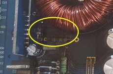
Did you check the capacitors and diodes near the 21844s?
Did you check all of the large low value resistors near the driver board?
Did you check the capacitors and diodes near the 21844s?
Did you check all of the large low value resistors near the driver board?
I don't for certain if it's a problem but those driver ICs have a minimum voltage of 10v. 10.2 is too close. IT may not be a problem but it should be eliminated as a problem.
Did you check the capacitors and diodes near the 21844s?
Did you check all of the large low value resistors near the driver board?
I have another 2 ohm current limiting resistor i made it parallel. now i am getting 11.2v on pin7 of 21844 so voltage is not a problem.
I have checked all diodes around 21844 and all big low ohm resistors and all are good.
I have checked for any smd capacitors around 21844 for any shorts but i did not find any.
Did you check/replace the components below?
I have checked those big resistors and it was good. And diodes good also.
With no output FETs, do you have low-side drive at the outputs?
i dont have any drive on the outputs without FETs on board.
With no output FETs, do you have low-side drive at the outputs?
Is there anyway I can isolate the problem? I am clearly not seeing any bad components on driver board.
The 2-3 jumper has to be removed to enable the driver IC. Have you removed it?
Yes I removed it.
With drive signal on pin 1 and 12v across 5 and 7, I'd expect to see drive out of pin 6 . That drives the low side outputs.
With drive signal on pin 1 and 12v across 5 and 7, I'd expect to see drive out of pin 6 . That drives the low side outputs.
Is the drive signal I post for pin1 is correct? That is how it will oscillate on negative side?
It looked OK. The output from the low side will be inverted but since you're only using one input to the scope, it should look essentially the same as the input drive signal.
It looked OK. The output from the low side will be inverted but since you're only using one input to the scope, it should look essentially the same as the input drive signal.
Pin2 of IRS21844 is shutting down the IC. the voltage on it is 0.4v black probe on negative rail. I too have power supply fets gettinng hot.
What can trigger pin2 to go low?
Do you read low resistance between the collector of either MAX transistor to pin 2?
Yes sir, the top max transistor collector to pin2 is 0.5ohms.
That transistor could be defective or it could be that something is driving it on and shutting the IC down.
That transistor could be defective or it could be that something is driving it on and shutting the IC down.
The power supply fets are IRFZ44N and gate resistors are 69ohms. without driver board they are getting hot?
it have drive signals on every gate.
- Status
- Not open for further replies.
- Home
- General Interest
- Car Audio
- crunch pzx5000.1 Schematic Request