geoturbo,
any news, I am curious about your repair of the amp?
When you install new resistors and transistors, you should have half of the voltage on each rail referenced to the ground, when you have these situation, I hope you'll have then posibility to adjust idle current on positive and negative side.
any news, I am curious about your repair of the amp?
When you install new resistors and transistors, you should have half of the voltage on each rail referenced to the ground, when you have these situation, I hope you'll have then posibility to adjust idle current on positive and negative side.
Thank you @pitbul, I sourced the resistors, I will hopefully find the time to substitute the resistor ladders over the weekend. Btw, how could I measure actual voltage drift? I took all previous measurements with negative probe on a center pad in the input board as a reference. Should I measure this pad let's say from both negative amp outputs to see actual status/if there is a significant drift?
In the meanwhile I substituted all four pre-driver transistors (q317 and q319 on both channels). Turned out that voltage over the four diodes stack (d301,2,3,4) was only 50mV. Then found q318 was shot, substituted it and now the voltage over the four diodes stack is 0,8V.
This voltage is 1,7V in the other channel (was about 2,4V when it was possible to set the bias current correctly).
Now it is not possible to issue high side bias on both channels, while Low side bias and Odep+ and Odep- all seem to be working for both channels.
Btw, I noticed there is continuity over d313 (pulling up one leg of the diode it measures ok), is this 0V correct or shall a different value be measured?

geoturbo, please put your voltmeter black probe on gnd (this is minus of your speaker) and red probe on Vcc+, mark that value,
another step is to put your red probe on Vee- and mark your value, sum of that two values will give you full voltage on +/- of your power supply (filter capacitor).
That is your voltage what you have to be 1/2. If you don't have 1/2 you will have to make it with divider what you will insert (new resistors) and if necessary put variable resistor and adjust what I wrote. As you can see middle of resistor network is connected to the gnd.
I see that you didn't understand me, but if you do what I wrote, you will have some results.
Hi,
I'm working on a similar project, getting a MicroTech 1000 back to life. It's a really old one, branded as Amcron for the European market (I think it's near 30 years old).
I've already managed to get it back up and running, the FanFormer had problems starting up, causing whole lots of noice but no correct 15V circuit.
That I've resolved in the meantime.
I'm now going through tests, doing the measurements and configurations. There was working on similar as you guys are discussing, the ODEP an BIAS.
Using manual and diagrams, I've been able to set up the ODEP voltages correctly, however I'm having problems with the BIAS.
I can locate the corresponding R (3/4) 02 and R (3/4) 21 resistors and they measure off (200 and 400mV), so I need to adjust the potentio meters R (3/4) 21 and R (3/4) 23 to get them in the 300/320mV range.
It might be me...Maybe I'm blind... But I am unable to locate those potentios. They should be on the output board. Or are there MT boards without adjustable BIAS?
Board number is P-10053-O
Many thanks if you would be able to give me a hint 🙂
Regards Jan
Sorry guys my patient has not been on the table lately, no positive news.. but will give an update some time..
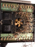
@JwBroumels trying to insert a picture from this iPad.. hopefully I get it correct showing the pots from the underside of the output board
@JwBroumels trying to insert a picture from this iPad.. hopefully I get it correct showing the pots from the underside of the output board
Attachments
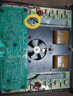
Thanks for the reply @geoturbo ,
Looks like my MT has a quite different board.
A lot of the schema compares, but not all.
Attached a photo of the layout.
It looks sick, has been smoking 20 packs of sigarets a night for many years.
I’ve got it from a night club, where it had played 1993-2010 every weekend, without a failure. It was used as a “mid” amp only, so not much pressure.
There are several more I can get, but I wAnt to be sure I can get them back up and running.
I do believe they prove their strength. 30 years old, 12 years unused, and 3 hours of work, they seem pretty healthy again.
Hope this board makes some sense, as attached