I'm having a real fun time with this amp...
I had it all working, then due to an issue with the preamp it got hit with a DC pop and it went and stayed DC, even with the preamp disconnected. I checked all the transistors with diode check and they all passed. Not sure what happened. All electrolytic caps were replaced. No fuses blew, but when I hook it up with the dim bulb tester I get a fully bright bulb even with a 200W bulb. (but the other channel works if I take the fuses out of the problem channel)
Not sure how to approach it now but I guess I just need to keep going through it. Not sure what people here can offer, but any advice on troubleshooting techniques for such issues would be welcome.
One thing I noticed, is there is no DC blocking on the input at all?? Should I add this?
Attachments
The DC300 is designed to produce DC current for loads like actuators. DC motors that control things like throttles on diesel motors. The actuator works against a throttle return spring. DC300 gained popularity in the seventies for rock bands due to the vast power and rugged heat management. The competition was products like PhaseLinear 700 and SWTC Tigersaurus, known for melting down on stage when stressed.
In no case past 1980 IMHO should a crown DC300 be connected to a speaker. Speakers are destroyed by DC. Bass drivers in the class of a 150 w/ch amp are ~$150 each, up. Usually mounted in cases in quads, as the 4-12 bass unit so favored by bar bands.
You will notice around the op amps, DC balance potentiometers. In the decade or longer life scenario, pot wipers oxidize and lose contact. So the device is doomed to produce DC, IMHO. Your problem may not be that, but if you solve all component failure issues, that possibility still looms. There is no DC out detect, as prof PA amps have. There is no speaker disconnect for DC on output, or even a crowbar SCR to blow the fuse.
If I had one, I would salvage case, power transformer, heat sinks, fan, input & output connectors. Some other driver circuit should be installed. I don't have the geometry measurements to suggest a particular one.
There are a couple of threads that discuss repair of the DC300 part by part. https://www.diyaudio.com/community/threads/crown-dc300a-help-with-repair.302595/
I'm wasting my time on a Peavey 650 w/ch amp more suitable for upgrading. I have repaired a couple of CS800s for 260 w/ch, which had minor problems with leaky PS capacitors & blown protection resistors (or thermistors). Also blown input board caused by plugging a 70 w guitar amp in the line level or microphone input. Cost me about $150 each dead. Much more worth the money, with the DC protection relays worth about that much, since they are known to be capable of actually protecting a speaker (Enzo said so).
Best of luck.
Last edited:
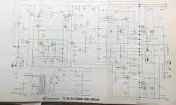
Sounds like you fried the input. Your schematic is not the expected op-amp based DC300. The uA739 used in DC300s is not exactly a standard op-amp, and pre-dates the current standard general-purpose op-amp. If your amp is actually the op-amp version, replacing the op-amp may be a supply issue today. If not, I would suspect the input transistor(s) Q101 have been zapped.
+1If I had one, I would salvage case, power transformer, heat sinks, fan, input & output connectors. Some other driver circuit should be installed.
Or with a little work it would make a very good truck battery charger
I thought I checked those, but maybe I missed something. Knowing that maybe I can focus on the input is helpful though. (And it doesn't have an op-amp. The schematic pictured is from the documentation the client gave me, I couldn't find that one online)Sounds like you fried the input. Your schematic is not the expected op-amp based DC300. The uA739 used in DC300s is not exactly a standard op-amp, and pre-dates the current standard general-purpose op-amp. If your amp is actually the op-amp version, replacing the op-amp may be a supply issue today. If not, I would suspect the input transistor(s) Q101 have been zapped.
I have also replaced the trimpots.
Can I add a highpass filter to the input? A first order filter right at the input?
I need to get it working but then I'm never touching one of these again. I do this full time and I'm at the point where I need to identify which projects will waste time and avoid those.
Transients can cause oscillation in an unstable amp, which could in theory blow the output stage. Simplest thing to do is power it down, let suffcient time pass for all the caps to discharge, then start making detailed comparisions between the good and bad channels using the resistance range on your multimeter. There has to be difference since one channel is faulty.
I'm still having trouble figuring this thing out.
The input transistor (which is 2 transistors in one package) tested good but I replaced it anyway. Also replaced the 2 18V zener diodes.
I've found some mismatched voltage readings but I'm confused by them. The input side of the 187k feedback resistor measures 10k resistance to ground (correct) but the other side measures infinite. But the resistor is okay, and I replaced it after finding this. The resistance starts low then climbs when I put the meter on it like when you put the ohm meter on a capacitor.
Also, the supply side of R138 (5.6ohm) measures high resistance to ground on the bad side, but about 150k to ground on the good side.
Some of the high voltage readings seem a bit weird due to stray voltages that are left in the circuit or introduced by the meter.
Does this give any good clues? I don't think anything is shorted and I'd previously pulled and checked all transistors. It is a pain to check the outputs as the wires are soldered directly to them.
I've done these measurements with all the rail fuses removed.
I have a good method for troubleshooting amps gone DC that works great but hard to do here because everything is wired in. I start pulling the same transistors in both channels and compare voltages. I keep pulling transistors until I've isolated the difference enough that I can find it. If I tried that in this amp I'd just make a mess of it.
Yeah, that does happen. Sometimes you have to reverse the polarity of the leads to get similar readings or wait for caps caps in the circuit to charge up before a resistance reading looks OK. You determine if it's OK by estimating what it should be from the circuit. But but the bottom line is you should get similar behaviour at the same points on both channels. If one differs, you need to investigate why. I've found and fixed some very tricky issues using this method. Just keep doing the comparisons, but keep the voltages out - make sure the system has been powered off for a while. The diode range on your meter can also be useful to check all the semiconductors. You didn't say how much DC was on the output? If it's swung hard to one rail, then you're looking for something catastrophic like a semiconductor failure. If it's just off by a few volts, then you're more likely looking at input stage balance issues etc.

When it is on the DBT, there isn't much voltage because the bulb is fully bright.
Without the DBT, I think it had swung hard but I forget. I'm nervous to take it off the dbt now. But it didn't blow, it was just DC.
I think even the voltage the ohm meter is putting into the circuit is staying there and throwing off readings? Is that possible. I'm using a Fluke. I have a 115 and a 117.
My gut thinks something has gone open.
Joke inside.
Build an Hiraga 8W "Le Monstre", power it with two truck batteries and recharge the batteries with the Crown.
Sorry i couldn't resist ...
Build an Hiraga 8W "Le Monstre", power it with two truck batteries and recharge the batteries with the Crown.
Sorry i couldn't resist ...
Sounds like fun, but I'd rather just throw it off a bridge at this point. There's loads of stuff around here I'd rather be working on.
Finally got this thing working again. Missed an E-C short in one of the transistors on the board.
Can I add a simple 1st order RC highpass filter of about 1Hz at the input of this amp? Is there any reasons I can't do that?
Can I add a simple 1st order RC highpass filter of about 1Hz at the input of this amp? Is there any reasons I can't do that?
Congrats on getting it working. No reason not to cap couple the input. I think people are a bit harsh on the amp. They were sold in hifi shops and have been used successfully in both home systems and industrially for decades. They're generally reliable. Many amps have been produced without DC protection, but with AC coupled inputs. When they fail, the problems are no different. Usually fuses save the day. It's not as popular today, but fuses inline with your speakers are a good idea that doesn't affect SQ all that much.
I've added an RC filter. After the gain control. 150kohm resistor to ground, then a 1uF cap between the gain pot and the board. Resistor is on the input side of the cap. Just in one channel for now.
I'm still using this on the DBT. Currently got a 200W bulb. When the caps discharge enough, and I power the unit on, I get a bright bulb and DC on the outputs. But if I power it on with the cap shorted, it is fine. And if I turn it on again before the caps have bled down it is fine. Maybe it would be okay off the DBT and this is just a weird reaction to the current limiting? But I don't want to damage anything again.
It seems this changed something the circuit wasn't expecting? Does anyone have an explanation? Should I do this differently?
Here's a quick drawing.
Attachments
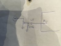
I suspect there is a small input offset error, so there is likely a turn-on thump: the added DC block cap passes current until it settles to the input offset error.
Try an experiment: set input gain to 0, and connect a clip lead across your blocking capacitor. When you lift the the ungrounded end of the clip lead, I predict you'll get a thump and a click/pop when you restore the connection. Try adjusting the input bias pot R103 to minimize this transient glitch. Once minimized, there's an output offset pot (R121) to trim output error.
Please let me know if this helps. Good luck!
Once the unit is on, shorting/removing the short on that cap has no effect.
When I turn it on from cold with the cap in place, I get DC to both speakers as well (with the DC blocking on only one channel). Forgot to mention that.
Fixed the issue with the preamp as well, bad op-amp led to a pop when treble turned all the way to one side.
When I turn it on from cold with the cap in place, I get DC to both speakers as well (with the DC blocking on only one channel). Forgot to mention that.
Fixed the issue with the preamp as well, bad op-amp led to a pop when treble turned all the way to one side.
So if I understand correctly, input offset is already well adjusted. At power on, there's initially DC present at speakers but it eventually settles to near 0V, assuming output offset has been trimmed?
If this is the case, it appears that the initial DC error may be the nature of the beast, since output presumably settles to nominal as the amp settles to equilibrium over the course of several minutes. Does this sound like what's transpiring?
BTW, how large initial output error?
If this is the case, it appears that the initial DC error may be the nature of the beast, since output presumably settles to nominal as the amp settles to equilibrium over the course of several minutes. Does this sound like what's transpiring?
BTW, how large initial output error?
Last edited:
Getting 3-5V DC on the output. Since the bulb is bright the rails are being dragged way down I assume. Didn't leave it on long enough to settle, but it didn't seem to be doing that.
The offset adjustments are set well.
The offset adjustments are set well.
The DC filter must have changed the impedance in a way the amp doesn't like? Maybe it would be okay off the DBT but I really don't want to take that chance and have to track more faults in this thing.
- Home
- Amplifiers
- Solid State
- Crown DC300 power amp issues