I build a simple line-level tube pre-amp for fun (usually keep to instrument amplification 😉). Common cathode (12at7) with a DC coupled cathode follower (12au7). Amplification factor of around 4. I'm measuring some crosstalk between the left and right channel. I guess capacitively coupled(?) since it gets worse with higher frequencies. I'm now trying to find the origin. Less is better, I get that. But how much is considered acceptable? Currently it's around -64dB @ 2kHz and -50dB @ 10kHz below output level. I'd hate to be chasing after unrealistic figures.
Like, 20dB. They're going through air into your own ears anyway!
More important might be to control the high frequency response, so it's not peaking (especially not one channel into the other). But that's no big deal.
You can also invert the channels, and couple some of the inversion into the opposite channel, thus "over-separating" the channels (which really means separation goes down again, but at a different phase angle).
I wouldn't worry about it, but if it's annoying, it shouldn't be too much trouble to add shielding to keep them better separated.
Tim
Sorry guys, been away for a couple of days.
@RJM1: Ok, I'll make a screenshot later (not at home right now). And yes, both channels are fed by the same power supply. With adequate decoupling of course.
@Sch3mat1c: This project is more of an exercise, so audibility is less a concern. It's more about understanding how to optimize a circuit. Seeing more crosstalk in the high frequency range makes me wonder why and where it happens, and how to improve on it.
Stray capacitance between circuit nodes, especially high impedance points.
Inductive coupling between circuit loops, expecially from where high currents flow.
Both of these rise with frequency.
Inductive coupling between circuit loops, expecially from where high currents flow.
Both of these rise with frequency.
Stray capacitance between circuit nodes, especially high impedance points.
Inductive coupling between circuit loops, expecially from where high currents flow.
Both of these rise with frequency.
Makes sense. I notice I have a hard time determining what those points are in my circuit/pcb.
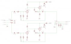
As requested, the scheme. The PSU is a Maida type, with regulated DC heater supply.


Why use two valves for one channel, inviting HF cross-talk? Use one valve per channel. That will avoid any cross-talk, what you could possibly get with about 3pF between the Anodes below 10MHZ I don't know. R101 and R201 should be, as grid stoppers, physically on the grids not before R102, 202! There is no advantage with DC heaters. Not enough gain to worry about if you have a faulty valve with Heater Cathode leaks.
Last edited:
The cross talk between the two triodes in a twin-triode valve is quite significant. There was an interesting thread about that here:
http://www.diyaudio.com/forums/tubes-valves/260477-crosstalk-between-triodes-dual-triode-tubes.html
http://www.diyaudio.com/forums/tubes-valves/260477-crosstalk-between-triodes-dual-triode-tubes.html
Good stuff, thanks! The 12at7 into 12au7 just came to be. No specific reason, just experimenting. I'll keep the advice in mind. Concerning R101/102, R101 is also used to isolate the feedback path from the input, not (just) as a gripstopper, but good idea to add an additional grid stopper.Why use two valves for one channel, inviting HF cross-talk? Use one valve per channel. That will avoid any cross-talk, what you could possibly get with about 3pF between the Anodes below 10MHZ I don't know. R101 and R201 should be, as grid stoppers, physically on the grids not before R102, 202! There is no advantage with DC heaters. Not enough gain to worry about if you have a faulty valve with Heater Cathode leaks.
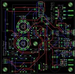
I fail to see how a ground plane will reduce crosstalk. I tend to steer away from groundplains, since they make it very difficult to control where currents flowIt seems that your pcb does not have any common ground layer. I think that is the main reason for cross talk.
Anyhow, the problem is caused by the layout reasons, not by ciruit it self.
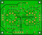
Below is an example of how the ground layer should be implemented.
View attachment 537123
I'll have a read, thanks!The cross talk between the two triodes in a twin-triode valve is quite significant. There was an interesting thread about that here:
http://www.diyaudio.com/forums/tubes-valves/260477-crosstalk-between-triodes-dual-triode-tubes.html
...I fail to see how a ground plane will reduce crosstalk. I tend to steer away from groundplains, since they make it very difficult to control where currents flow...
A tube amplifier built on the pcb is not critical for ground loops like it is when typical point-to-point is used.
Therefore one side of the pcb can be fully (or almost) used as a ground plane without any hum or such problems.
But the pcb should be connected to metal chassis at one point only.
The attaching screws or posts of the pcb should be isolated from the ground plane of the pcb.
Last edited:
The cross talk between the two triodes in a twin-triode valve is quite significant. There was an interesting thread about that here:
http://www.diyaudio.com/forums/tubes-valves/260477-crosstalk-between-triodes-dual-triode-tubes.html
Note that it will be better for shielded and RF types, like 6CG7 and 6DJ8, and better for low Rp types (like 12AU7 vs. 12AX7), and better where capacitance in general is smaller (like 12AT7 vs. 6SN7).
Where Cp1-p2 is given in the datasheet, the crosstalk can be calculated simply. Take the equivalent parallel resistance of each plate (i.e., Rp || RL || Rleak || ...), connect them in series with Cp1-p2, and run the numbers for an impedance divider (that resistance into Xc) at whatever frequency of interest.
Obviously, for shielded types, this assumes you've connected the shields to ground, as specified in the datasheet. Don't leave them floating!
Anyway, most times you'd use a dual, you should try to use both halves in the same channel (e.g., pentode/triode for gain + phase splitter) rather than dual duty. Much easier to wire up, anyway!
Tim
A tube amplifier built on the pcb is not critical for ground loops like it is when typical point-to-point is used.
Therefore one side of the pcb can be fully (or almost) used as a ground plane without any hum or such problems.
But the pcb should be connected to metal chassis at one point only.
The attaching screws or posts of the pcb should be isolated from the ground plane of the pcb.
But ground loops are not the only concern when it comes to grounding are they 🙂. But besides that, my original question remains; how does a ground plane reduce crosstalk. If anything, I would think it could increase crosstalk, since currents from one channel through the groundplane, could potentially 'mess' with the ground point of another channel.
Good tips, thanks.Note that it will be better for shielded and RF types, like 6CG7 and 6DJ8, and better for low Rp types (like 12AU7 vs. 12AX7), and better where capacitance in general is smaller (like 12AT7 vs. 6SN7).
Where Cp1-p2 is given in the datasheet, the crosstalk can be calculated simply. Take the equivalent parallel resistance of each plate (i.e., Rp || RL || Rleak || ...), connect them in series with Cp1-p2, and run the numbers for an impedance divider (that resistance into Xc) at whatever frequency of interest.
Obviously, for shielded types, this assumes you've connected the shields to ground, as specified in the datasheet. Don't leave them floating!
Anyway, most times you'd use a dual, you should try to use both halves in the same channel (e.g., pentode/triode for gain + phase splitter) rather than dual duty. Much easier to wire up, anyway!
Tim
- Status
- Not open for further replies.
- Home
- Amplifiers
- Tubes / Valves
- Crosstalk L-R. Acceptable levels?
