Final Test Data including 12AX7
just to summarize the final test data revisions and include the 12AX7 that someone suggested should be tested. i dont plan to test anything else, but would like to hear any comments on the final posts.
just to summarize the final test data revisions and include the 12AX7 that someone suggested should be tested. i dont plan to test anything else, but would like to hear any comments on the final posts.
Attachments
Are you saying you switched off the B+ to the test triode and you STILL measured a signal from the anode? That would imply most of the coupling is anode-to-anode, not anode-to-grid.In addition to the above tests, the supply voltage to the plate of the Test Triode was set to 0 volts and with either 0ohms or 1Mohm impedances on the Test Triode grid, similar results to having the Test Triode at 0 ohms and Vp=180VDC was recorded.
How do you gte such a high level of anode-to-grid crosstalk when the grid is shorted to ground? Resonance possibly, but at such low frequencies this seems unlikely. Also, why does the crosstalk seem to decline so much at 1MHz? Logically it ought to be greatest! This puzzles me.
By the way, you forgot to say how big the input signal from the generator was. I'm guessing 100mVpp?
you have several questions in your reply.
regarding switching of B+ to test triode and getting signal at the anode of the test triode: Agree. the coupling is anode to anode. the grid of the test triode would be effectively out of the circuit for all intensive purposes. that is why shorted or with a 1 Mohm resistor input does not change the result. note that the signal at the anode of the test triode is 4 mVp-p at 1kHz and up to 60mVp-p at 100kHz. small compared to tests with B+ on test triode and inputs of 47k and 1m.
Regarding the "high level of anode to grid crosstalk when the grid is shorted to ground": Incorrect! the signal at the anode of the test triode when the test triode is shorted to ground is 4 mVp-p at 1kHz and up to 60mVp-p at 100kHz. small compared to the tests with inputs of 47kohm and 1Mohm. perhaps i need more understanding what you are saying.
Regarding "crosstalk seem to decline so much at 1MHz": First, i was sloppy on my test methods. i did not increase the input from the signal generator so that the input level was maintained at 100mVrms. if i was back at university, i would do this again, but i already got the degree, so i choose to be lazy. second, i am going to make an assumption that the frequency response of the driver triode amplifier trails off after 100kHz at some frequency and the resultant frequency response at 1mHz is as shown. let me know if this solves the mystery.
Regarding the input signal: i set it at 100mVrms. the 'yellow' trace on the documents show a signal amplitude of 282mVp-p.
looking forward to your reply. thanks.
OK that makes sense now.regarding switching of B+
I understand now. I was thrown by the phase which appears to be 180 degrees at 100kHz? If it is anode to anode, you would expect it to be around 90 degrees falling to zero at very high frequencies. Strange...Incorrect! the signal at the anode of the test triode when the test triode is shorted to ground is 4 mVp-p at 1kHz and up to 60mVp-p at 100kHz. small compared to the tests with inputs of 47kohm and 1Mohm.
Yes, that makes sense now, if you didn't maintain the same input level, Miller capacitance would bring it down.i was sloppy on my test methods. i did not increase the input from the signal generator so that the input level was maintained at 100mVrms. the frequency response of the driver triode amplifier trails off.
Very interesting to see that the 6SN7 is so much poorer than the 12AX7. I would never have predicted that.
phase which appears to be 180 degrees at 100kHz? If it is anode to anode, you would expect it to be around 90 degrees falling to zero at very high frequencies. Strange...
Dont you mean 180 degrees falling to zero? remember the yellow trace is the signal at the grid of the driver triode which would be inverted at the anode of the driver triode thereby the two anodes for the two triodes would then be in phase.
Yes, that makes sense now, if you didn't maintain the same input level, Miller capacitance would bring it down.
i learned something..... the Miller capacitance causes the loading of the signal generator..... thanks.
Very interesting to see that the 6SN7 is so much poorer than the 12AX7. I would never have predicted that.[/QUOTE]
and yes it is interesting the 12AX7 is better. i looked at the construction of the 12AX7 i tested and it looks like a generic 12AX7.....
sorry about the last post organization. i havent figured out how to parse out quotes yet.........
Dont you mean 180 degrees falling to zero? remember the yellow trace is the signal at the grid of the driver triode
Oh. Well that sure makes more sense. That's not what you drew in your schematic!!

Very interesting to see that the 6SN7 is so much poorer than the 12AX7. I would never have predicted that.
and yes it is interesting the 12AX7 is better. i looked at the construction of the 12AX7 i tested and it looks like a generic 12AX7.....[/QUOTE]
12AX7s can vary in their internal construction considerably.
I tested another SE stereo amp (single 7n7 driving a pair of 801a). On one side, I get 60dB or more separation with the undriven input at 300k, input to common. Switching sides, I get similar results at 200 and 2k Hz, but about 45 db separation at 20kHz. If I short the undriven input, the output is down 60dB or greater. In all cases the crosstalk is 180 degrees out of phase. The difference, on side to the other, could be do to component or wiring proximity or tube internals?
I don't know if the 7N7 is different in regard to crosstalk than a 6SN7. The 7N7 (loctal) has a metal base, which is grounded.
My take-away is that the channel separation is more than adequate in a practical application.
Sheldon
I don't know if the 7N7 is different in regard to crosstalk than a 6SN7. The 7N7 (loctal) has a metal base, which is grounded.
My take-away is that the channel separation is more than adequate in a practical application.
Sheldon
A true crosstalk measurement is with the I driven channel loaded to approximately what the impedance would be when in use. 47k would be good for a 100mv input. Something smaller equiv to a cartridge impedance for a phono input
I would check to see what the problem is if the two channels aren't matched
I would check to see what the problem is if the two channels aren't matched
Don't you have to take into account the output impedance of the driving device, in parallel with the input impedance? It would normally be much lower. I measured the worst case, with a high impedance at the input.
Sheldon
Sheldon
My research of crosstalk suggests the impedance one plugs into the input should be close to what would be used in normal conditions. So if your input is a moving magnet cartridge use the equiv impedance. In my case, the normal impedance that would be attached to the test triode amp would be the equiv of the preceding section of the amp, which will be a 6C45pi raising the signal to about 100mV. Perhaps someone else may have a more exact of what input impedance should be used for the channel of the amp where the crosstalk is measured
Perhaps someone else may have a more exact of what input impedance should be used for the channel of the amp where the crosstalk is measured
Both driven and measured channel should be similar to actual use conditions.
Sheldon
Thanks
Thanks all but specialy mixolydian for this very usefull thread. It helped me a lot to understand some fenomena and results.
Keep sharing the good work!

Thanks all but specialy mixolydian for this very usefull thread. It helped me a lot to understand some fenomena and results.
Keep sharing the good work!
Sheldon, thanks for your data on the differences you are having between channels. wonder if there is differences in the layout between the channels that is causing the differences in crosstalk. i am going to make the next project with care on ensuring the layout is same for each channel and give it a test. it is strange that the crosstalk from one channel to the other is different when you test it the other way. agree, that the levels you are detecting are well below where it should cause an issue while listening.
Sheldon, thanks for your data on the differences you are having between channels. wonder if there is differences in the layout between the channels that is causing the differences in crosstalk.
Quite possibly. I couldn't spot any obvious differences. It could even be that some crosstalk is from transformer to transformer. One possible clue is that the crosstalk is exactly 180 degrees out of phase at all frequencies, but I haven't thought deeply about that.
Another potential is that the intermodulation is due to power supply load (stereo amps, single shared power supply in one case, split after main into separate LC networks for the other). Don't know why that would differ between channels.
it is strange that the crosstalk from one channel to the other is different when you test it the other way. agree, that the levels you are detecting are well below where it should cause an issue while listening.
When I switch the input tube, the difference remains. So unless the double triode is asymmetric in some way, it suggests an alternative source of crosstalk. As you say, the levels were very low, so I didn't pursue further.
Sheldon
Last edited:
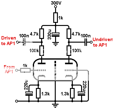
I finally got around to measuring some crosstalk myself, in a 12AX7 and 6N2P, using an Audio Precision System 1. The input signal level was adjusting to get 10Vrms at the anode of the driven valve, at 1kHz.
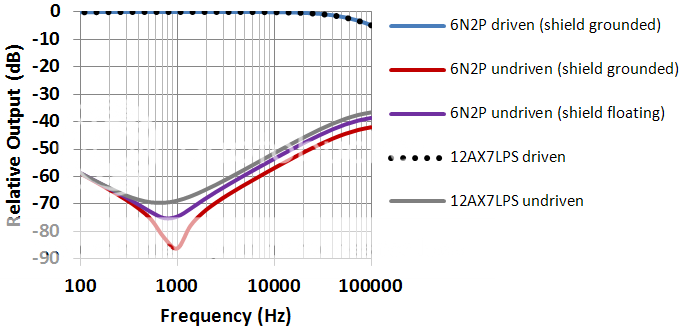
The plot shows the frequency response at the driven and undriven anodes. At high frequencies you are looking at genuine crosstalk between the anodes, while the rise at low frequencies is due to the common source impedance of the power supply.
Not surprisingly, the lowest crosstalk is with the 6N2P shield grounded, although leaving it floating only degrades the figure by 3.5dB. The 12AX7 has larger anodes so it is reasonable to expect it to have greater capacitance betweenn them, and therefore the worst crosstalk.
My back of envelope calculation suggests anode-anode capacitance of about 1.3pF for your 12AX7. This seems vaguely plausible, although maybe a bit high?
Interesting that only the shielded 6N2P shows the expected near-null where the phase delayed crosstalk via the 330uF cap cancels the phase advanced crosstalk via Caa.
Interesting that only the shielded 6N2P shows the expected near-null where the phase delayed crosstalk via the 330uF cap cancels the phase advanced crosstalk via Caa.
The 12AX7 is down 60dB at 4kHz, so I estimate 0.5pF, which also gives the right resonant frequency in sim. Anything in that area sounds reasonable to me, given the valve socket and associated wiring.My back of envelope calculation suggests anode-anode capacitance of about 1.3pF for your 12AX7. This seems vaguely plausible, although maybe a bit high?
Yes, that is curious...Interesting that only the shielded 6N2P shows the expected near-null where the phase delayed crosstalk via the 330uF cap cancels the phase advanced crosstalk via Caa.
I used 50dB down at 10kHz for my calculation, and assumed the net impedance seen at each anode is 40k.
- Status
- Not open for further replies.
- Home
- Amplifiers
- Tubes / Valves
- Crosstalk between Triodes in Dual Triode Tubes