Hi all
Ive just joined this site after finding it very informative. Im looking for help and advice with a few projects as I am new to DIY audio
Ive recently bought a pair of RTL TDL2s which I plan on using as the basis for a few projects. I was first thinking of upgrading the crossovers as I know they are a tad on the cheap side in these speakers. I would like to build my own crossovers using quality components. Ive been looking at what is available at Hi-Fi Collective but to be honest I wouldn't know where to start for the best.
If there is anyone who has done similar or has experience of using some of the components available above I would love to hear from you. I may eventually upgrade the drives too.
Thanks🙂
Hi,
In my experience unless you know what you are doing your wasting
your money. Possibly upgrade the tweeter caps if they are cheap.
New drivers will need new crossovers, and unless you understand
the cabinet design, you can't simply upgrade the bassmid unit,
and upgrading tweeters is usually an exercise in futility, though
it is generally much less likely to go badly wrong in reality.
rgds, sreten.
http://www.falconacoustics.co.uk/
Last edited:
Hi sreten and thanks for reply
My sentiments too!! I was thinking of making a call to Wilmslow Audio as they make a kit that is a direct replica of the RTL3, which I believe had the same bass/mid driver as the 2s. Their kit uses different drivers so I was thinking along the lines of using them, if i get that far! I think the problem with the standard crossover network is just that they use cheap components and it appears at high volume they reach saturation. My start point was to upgrade the caps for a higher rating, I wouldnt want to start changing the crossover point!! Ive checked out falcon, they have some nice kit!
Cheers😉
Hi,
IMO FWIW if you buy used speakers and want to upgrade don't mess about.
Sell them, add the cost of your upgrade, and buy simply better used speakers.
You don't know at all if its the x/o reaching saturation limits or the drivers.
Higher voltage capacitors are pretty much a waste of time as an idea.
It would take an extraordinarily inept manufacturer to build speakers
where the x/o gives up the real ghost before the drivers actually do.
A high power x/o at best here would only help out a little.
rgds, sreten.
Last edited:
Yeah, i hear what you are saying but they cost next to nothing, im more interested in having a play around just to see what the results are like
I also have a pair of TDL3 which appear to have the same drive units, just more of them. They do have a problem with melting crossovers. I have seen a few pairs in past advertised on Ebay with this exact fault and the pair I have are the same. They work fine ( I have an ok pair to compare them to) but the caps are falling apart due to heat damage. They have even started to melt the plastic back plate that holds the speaker terminals. You are probably right about the drivers too. Having been through a studio engineers course like to listen at what we call performance level, when i can. I noticed the other day that the back panels get quite hot when driven hard!! - that was the good pair too!
Im a big fan of PMC, and I am sure I remember reading one of their articles once where they claimed it was the crossovers that let a lot of lower priced speakers down. If I remember correctly TDL actually made their own drive units?
I think I might go and pull them apart now and have a look at cap values!!😉
Cheers
Re:'started to melt the plastic back plate" - speakers driven at that level should be using active crossovers, not passive
re:"like to listen at what we call performance level" - how long do you think your hearing will last?
re:"like to listen at what we call performance level" - how long do you think your hearing will last?
Hi all
Ive just joined this site after finding it very informative. Im looking for help and advice with a few projects as I am new to DIY audio
Ive recently bought a pair of RTL TDL2s which I plan on using as the basis for a few projects. I was first thinking of upgrading the crossovers as I know they are a tad on the cheap side in these speakers. I would like to build my own crossovers using quality components. Ive been looking at what is available at Hi-Fi Collective but to be honest I wouldn't know where to start for the best.
If there is anyone who has done similar or has experience of using some of the components available above I would love to hear from you. I may eventually upgrade the drives too.
Thanks🙂
The RTL TDL2 and TDL3 are good classic aperiodic designs that was well executed. The second order crossover should work well. The only thing that I can think off is to re-cap with good quality film capacitors. It is not necessary nor advisable to touch the other components.
The TDL3 has 2 woofers wired in parallel so that its low pass section is different from that of the TDL2. The tweeter padding resistors will be different too.
Since the Wilmslow Audio TL3 kit has the MTM configuration of the TDL3, it is not directly applicable to TDL2. And the driver parameters are different too.
There is an old post that should be helpful to you: http://www.diyaudio.com/forums/multi-way/107268-tdl-rtl2-upgrades.html
Last edited:
Capacitors shouldn't get hot. It isn't just that they don't handle heat well, but an ideal capacitor simply doesn't consume power.
Real capacitors have a very small resistance which can result in a small amout of heat. More likely they are soldered to a hot resistor or too close to the heat radiated from them. Inductors are the same as capacitors in this respect but they can get hot due to their resistance (which is an un-necessary but practical property of real inductors).
On the other hand an inductor with a core other than air might behave differently at higher power. If you went down this road and replaced one with an air core, and took a view toward maintaining the existing small parasitic resistance spec, just so it doesn't change anything, the air core would use a larger gauge of wire.
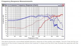
The reason the TDL crossover designs get hot is they have a shunt resistor across the 6" paper woofers:
TDL RTL Rebuild - Crossover and Measurements
As ever, without tracing a schematic you are wasting your time on "upgrades". Just piddling about with different quality components. 😀
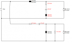
Below is the MTM TDL RTL 3. The similar woofers are paralleled, so component values change by a factor of 2. Ropey old design, IMO. I wouldn't do it that way. All sorts of problems there. A 6kHz LCR bass notch would work much better, and even just some shunt resistance in series with the bass capacitor would work better than that hot resistor.
TDL RTL Rebuild - Crossover and Measurements
As ever, without tracing a schematic you are wasting your time on "upgrades". Just piddling about with different quality components. 😀
Below is the MTM TDL RTL 3. The similar woofers are paralleled, so component values change by a factor of 2. Ropey old design, IMO. I wouldn't do it that way. All sorts of problems there. A 6kHz LCR bass notch would work much better, and even just some shunt resistance in series with the bass capacitor would work better than that hot resistor.
Attachments
Thanks everyone for your input.
It wasnt me that melted the back plate, they were like that when I got them!! The guy I bought them from said they made good party speakers!! Having seen a few pairs on Ebay with the same problem I was curious as to why.
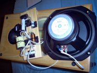
Thanks Steve. You are surely not the 'Steve' of System 7 fame???? In the article you posted you can see the pic of original rtl crossover. The blue cap in the center is the one on mine showing heat damage along with the resisitor so I guess the heat has come from the resistor like you said.
Having listened to both 2s and 3s, I can safely say the 2s are a much better sound - for me anyway
Thanks again everyone for your advice 😉
It wasnt me that melted the back plate, they were like that when I got them!! The guy I bought them from said they made good party speakers!! Having seen a few pairs on Ebay with the same problem I was curious as to why.
Thanks Steve. You are surely not the 'Steve' of System 7 fame???? In the article you posted you can see the pic of original rtl crossover. The blue cap in the center is the one on mine showing heat damage along with the resisitor so I guess the heat has come from the resistor like you said.
Having listened to both 2s and 3s, I can safely say the 2s are a much better sound - for me anyway
Thanks again everyone for your advice 😉
No relation, but I like Mr. Hillage's stuff. 😀
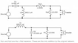
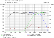
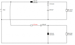
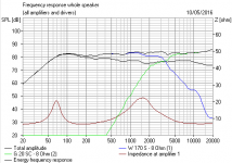
I made a guess as to what the TDL RTL2 crossover looks like.
I then redid it without the heat problems.
Lastly I redesigned the bass filter for the 6kHz notch on the 6" paper bass bass cone resonance, which cures a lot of problems. The tweeter filter can be fiddled with, but I went for a better amplifier load. The red resistor is select on test really. I don't know much about yours beyond it being a 94mm type like SEAS or Morel or Vifa.
One of my circuits last, to show how it is done. It's not hard. You get a better speaker. 😎
Attachments
Nice one, thanks Steve
I actually shook the Mr Hillages hand last year outside a System 7 gig, what a night!!!
Your post have been very helpful and inspiring so i will continue with this project. The link posted to a previous thread on the trl 2s was fantastic too, just goes to show what a small world we live in as one of the posters lives 10 mins away!!
What software are you using?
Already had a look at some cap and resistor upgrades - nearly died of shock looking at Audio Note copper foil signal caps!! Im going to defo dampen the cabs too so
Maybe see you at Hillage gig somedaym, shame about Dave Allen🙁 rest in peace brother
Thanks again Steve
Buying appropriate capacitors is somewhat beneficial, but if you don't like what you hear, look elsewhere. Cabinet damping is more important, as is your configuration of drivers, the acoustic design of the speakers and the room, the crossover circuit itself and others.Already had a look at some cap and resistor upgrades - nearly died of shock looking at Audio Note copper foil signal caps!! Im going to defo dampen the cabs too so
Equating capacitor price with sound quality is a fraught excercise. Resistors are even less of an issue.
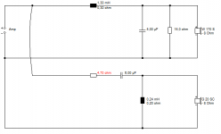
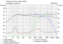
AllenB is dead right. Don't fret on component quality too much. I use 250V polypropylene caps and ferrite cores above 1mH. Neither is very expensive.
They work. You do want an aircore for the 0.2mH LCR, if you go that way. Resonant circuits amplify any non-linearities in my estimation.
AllenB is the great proponent of tuning by ear. It's not hard to adjust the input resistor to a tweeter circuit for level. 1 ohm is 1dB usually. 3dB is half power.
I'm pretty confident about that 6kHz notch. The resonance is at 5kHz. 😎
TDL RTL Rebuild - Crossover and Measurements
I use Boxsim for sims:
Downloads
The Visaton W170S 8 ohm ought to be close to what you have, but I'd measure the DC resistance (around 6 ohms) to be sure.
This Alto II would be a good start imported into Projekte folder. Then adjust it, and change the 4 ohm woofer.
Attachments
No relation, but I like Mr. Hillage's stuff. 😀
I made a guess as to what the TDL RTL2 crossover looks like.
I then redid it without the heat problems.
Lastly I redesigned the bass filter for the 6kHz notch on the 6" paper bass bass cone resonance, which cures a lot of problems. The tweeter filter can be fiddled with, but I went for a better amplifier load. The red resistor is select on test really. I don't know much about yours beyond it being a 94mm type like SEAS or Morel or Vifa.
One of my circuits last, to show how it is done. It's not hard. You get a better speaker. 😎
Wow just what I wanted/needed thanks system 7. I upgraded a pair of TDL RTL 2's and have the drivers just sitting a box in box. My idea was to put them in center speaker for my surround sound. I have 3 pairs altogether 2 x 2's and set of 1's. For the price..for me .. unbeatable should be worth a lot more.
- Status
- Not open for further replies.
- Home
- Loudspeakers
- Multi-Way
- Crossover upgrade/redisgn