Thank you for your advise guys. A simple 2ohm resistor in series on the mid solved 90% of the problem there. Im sure the rest will not be much of a problem either now, just need to wait for new resistors to come in.

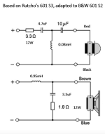
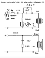
Hi everyone. I'm a beginner in making crossovers. I changed the original BW 601 S2 with Rutcho mode based on BW601 S3 (see attachment). The highs are no longer present as before, they are heard in the back, a scheme with the placement of the parts in the crossover to reach the target graph in the attachment can help a lot.
Attachments
-
 Actual upgrade Rutcho BW 601 S 2.PNG35.3 KB · Views: 130
 -
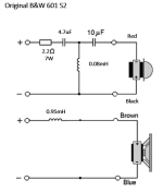 Original BW 601 S 2.PNG28.5 KB · Views: 126
 -
 Actual upgrade Rutcho BW 601 S 2.PNG35.3 KB · Views: 124
 -
 Original BW 601 S 2.PNG28.5 KB · Views: 120
 -
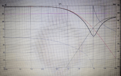
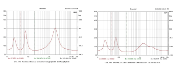 B&W 601 S2 original impedance left side versus target right side.png79 KB · Views: 122
 -
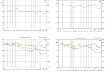
 B&W 601 S2 Original frequency left versus target right.png120.3 KB · Views: 134
With an impedance wildly swinging from 5 to 30 Ohms I'd avoid any class D amplifier with these.
Not impressed with the original crossovers, built to cost rather than purpose IMO.
I always thought B&W sounded boxy, but the advert spend in the HiFi magazines always gave the new model rave reviews, but I remember laughing when the previous model, previously perfect, was described as 'boxy' - something never mentioned when they were released!
So I'd consider bracing and woollen damping around the mid/bass, and maybe look at a better crossover, ideally with the crossover point away from the midrange.
Also some soundproofing pads on the back of the basket, to stop reflections back through the cone, ideally some triangular section sticky closed cell foam perhaps,
Thanks for the answer and recommendations. I focus on changing the ideal components to reach the frequency response (target) mentioned above in the attachment or something that can help in the crossover. I use a Yamaha CD player and a CR 420 solid state 4-16 Ohms amplifier.
Hello Steve.This is a good way of controlling breakup at 5kHz in this case: see attachment.
It's called a tank notch, and with 1mH coil you'd want 1uF and 22R for 5kHz. Really changes the sound entirely!
The resistor is important because without it you'd get a dead short at high frequency with a shunt capacitor across the bass.
It can also be applied to B&W 601 S 2 or or must it need some adjustments to the values of the components in the crossover, but to the schematic?
Thanks Petros.
Attachments
TBH, this is all very confusing with so many models of this speaker!
My understanding is that the 601 series had a 6" kevlar bass, and the 602 series a 7" bass.
Either way, a 22R and 0.68uF (maybe even 0.82uF or 1uF which takes the notch lower to around the 5kHz bass breakup) across the approx 1mH bass coil is worth the experiment. Hardly costly components.
https://www.soundonsound.com/reviews/bw-dm602-s3
The 7" 602 series, being loud at 90dB, doesn't give you much margin to improve the impedance on the 4 ohm tweeter. It's driven largely flat out around 90dB.
But I don't think anything will blow up if your amplifier is a good one. Most amps don't mind low impedance at the top end. It's low impedance in the bass that is an Amp-killer!
I think the 602 is a tricky and compromised speaker. Would much prefer an 8 ohm tweeter to be amp friendly.
Thanks for the reply Steve.
If I add an LCR before entering the crossover, are there any chances to improve the impedance and is it more friendly to the 4-16 Ohm amplifier?
Thanks for the answer Allen B.
Is it ok if I go slightly off-axis towards the low frequencies, changing the value of a resistor or capacitor?
Does a small 100nF capacitor add value to the 10uF capacitor?, but one more 10 uF in parallel over the resistance of 3.3 Ohms from the high input?
I will play with resistors of different values, of course simulating in VituixiCAD2 and then applying it to the crossover, and of course the listening test will convince me. If you have any other proposal to change even the design of the crossover, I will put it into practice with all my might.
It won't make much difference at lower frequencies.Is it ok if I go slightly off-axis towards the low frequencies,
The 0 degree axis isn't very significant in the bigger picture.

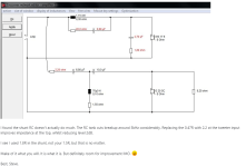
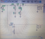
I am attaching the crossover made last night in VituixCAD2, the cutting point is ok to be at 4700 hz, how is it? is it better to go over 5000 hz? or to decrease to 4000, 3000 hz.
Please explain to me because I don't know how it behaves as a different sound than Rutcho, what an improvement
does from the point of view of the sound of the 4.7 ohm resistor and the 15 u capacitor on tweeter,and the rezistor 1.8 Ohm to inductor 0.08mH.
What other suggestions for improvement can be made? what else can be added or removed from the crossover?
Thanks Petros.
Attachments
What would this actually do to a class D amplifier ?With an impedance wildly swinging from 5 to 30 Ohms I'd avoid any class D amplifier with these.
Not impressed with the original crossovers, built to cost rather than purpose IMO.
I always thought B&W sounded boxy, but the advert spend in the HiFi magazines always gave the new model rave reviews, but I remember laughing when the previous model, previously perfect, was described as 'boxy' - something never mentioned when they were released!
So I'd consider bracing and woollen damping around the mid/bass, and maybe look at a better crossover, ideally with the crossover point away from the midrange.
Also some soundproofing pads on the back of the basket, to stop reflections back through the cone, ideally some triangular section sticky closed cell foam perhaps,
It affects the frequency response, because the LC filter output of them has to be matched into a constant impedance. Quite often the eBay ones are a bit screechy, and people dump a 16 R (etc) resistor across the speaker terminals to flatten the impedance.actually do to a class D amplifier
A solid state amplifier would ignore the impedance.
A tube amp would perhaps notice a little, but not too much.
@Petross. I recall Rutcho's 601 modification was this:

https://rutcho.com/tweaks/01_bw_dm601s3/bw_dm601s3.html
Your 0.08 mH tweeter coil is really not indicated... that is more 602 version.
I would be questioning of your tweeter 4.7R + 15uF too. It will drop impedance considerably, as will the 0.08mH coil. People don't do this usually, especially in that position.
Thanks for answer Steve. For beginning I try a 22R and 0.68uF (maybe even 0.82uF or 1uF which takes the notch lower to around the 5kHz bass breakup) across the approx 1mH bass coil is worth the experiment. Replacing 3.3R with 2.2R and 1.8 R to tweeter inductor 0.08mH, I hope for better sound stage and a correction o high freq.
AFAIK, B&W made three versions of both the 601 and bigger 602.
They fiddled around with modified drivers and crossovers in the later models which were around year 2000.
This, I THINK, is the original 601, going by the date and the NP Electrolytics:


Notice positive polarity on the tweeter. And 1.4mH bass coil. R56 means 0.56 Ohms. 0.15mH tweeter coil.
I am getting a severe headache from trying to sort out the total confusion on the Internet and diyaudio about this, and B&W don't seem to document models like they used to.
Rutcho says the 601 S3 is this in the original:

See what we are up against? 🙁
The tank notch works as the inverse product of the bass coil value and the small capacitor. 1.4mH and 22R plus 0.68uF will be around 5kHz. As is 1mH and 22R and 1uF. You follow?
What I would be doing is measuring your own 601 S2 crossover with a capable multimeter with an inductance scale. Takes out the guess work!
My concern is that you don't take the impedance too low.
They fiddled around with modified drivers and crossovers in the later models which were around year 2000.
This, I THINK, is the original 601, going by the date and the NP Electrolytics:
Notice positive polarity on the tweeter. And 1.4mH bass coil. R56 means 0.56 Ohms. 0.15mH tweeter coil.
I am getting a severe headache from trying to sort out the total confusion on the Internet and diyaudio about this, and B&W don't seem to document models like they used to.
Rutcho says the 601 S3 is this in the original:
See what we are up against? 🙁
The tank notch works as the inverse product of the bass coil value and the small capacitor. 1.4mH and 22R plus 0.68uF will be around 5kHz. As is 1mH and 22R and 1uF. You follow?
What I would be doing is measuring your own 601 S2 crossover with a capable multimeter with an inductance scale. Takes out the guess work!
My concern is that you don't take the impedance too low.
Last edited:
Hello Steve.
Thanks for the reply.
I will attach the original B&W 601 S 2 crossover that I have and will do for the bass coil of 0.95 mH tank notch 1mH and 22R and 1uF.
Regarding the multimeter with the inductance scale, I am going to decide on a model that has an ESR-meter.
Thanks for the reply.
I will attach the original B&W 601 S 2 crossover that I have and will do for the bass coil of 0.95 mH tank notch 1mH and 22R and 1uF.
Regarding the multimeter with the inductance scale, I am going to decide on a model that has an ESR-meter.
Attachments

You are on your own there, @Petross.
You have certainly lost me:

https://en.wikipedia.org/wiki/ESR_meter
Unless you have NP Electrolytics, I would lose no sleep over this issue.
You have certainly lost me:
https://en.wikipedia.org/wiki/ESR_meter
Unless you have NP Electrolytics, I would lose no sleep over this issue.
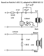
Hello Steve. I added the Jntzen Superes 1.8 Ohm 10 w non-inductive resistor to the 0.08 tweeter coil and a Jantzen audio 0.1uF capacitor to the 10 uF capacitor. I am satisfied with the sound after a weekend of listening, I noticed a better sound stage and the highs have returned after Allen B's recommendation to go slightly off axis I hope highs and with a crossover point at 4700 Hz.
In the simulations with a resistance of 22 ohms and a capacitor of 1 uF, the impedance dropped a lot and I gave up. Thanks for the recommendations.
In the simulations with a resistance of 22 ohms and a capacitor of 1 uF, the impedance dropped a lot and I gave up. Thanks for the recommendations.
Attachments
Hello everyone.
After a week and a half of listening to several kinds of music, I replaced the 3.3 ohm resistance in the high filter with 1.8 and the tweeter was too loud and aggressive. I only lasted 10 minutes after I replaced it with 2.4 and everything changed for the better (low treble is well placed and non-aggressive).
I declare that this is the sound I was looking for and maybe only a kit from GR research can be better better than that but it costs 500 US dollars. Everything is in the right place after listening to what I knew very well, such as fine details and the soundstage. Recommend for B&W 601 S 2. Crossover attached.
Thanks for all the advice. You are wonderful people who dedicate your time and knowledge to help and this is part of our purpose here in the world.
Attachments
- Home
- Loudspeakers
- Multi-Way
- Crossover mod surprising results