@Petross. Always nice when people get back with the result on a project. Not many do! So thank you.
Here is a summary of Rutcho's popular modification to a two-way B&W 601-S3:
https://rutcho.com/tweaks/01_bw_dm601s3/bw_dm601s3.html
Before:

After:

Now, that all looks like harmless fun in the tweak department, and worth a try!
HOWEVER.... when you try this with other 6" Kevlar 601 and vaguely similar 7" Kevlar 602 models, it needs a bit of thought.
Crossovers are different, and drivers are updated or modified. And the impedance problem with the 4 ohm tweeter limits what you can do.
But this all looks OK if this is your original 601-S2, and I don't know where you dug it up from:

Going to this:

I just have a doubt that the tweeter coil really is 0.08mH in your 601-S2. Needs measurement IMO.
Otherwise internet confusion will get worse! 🙁
Best, Steve.
Here is a summary of Rutcho's popular modification to a two-way B&W 601-S3:
https://rutcho.com/tweaks/01_bw_dm601s3/bw_dm601s3.html
Before:
After:
Now, that all looks like harmless fun in the tweak department, and worth a try!
HOWEVER.... when you try this with other 6" Kevlar 601 and vaguely similar 7" Kevlar 602 models, it needs a bit of thought.
Crossovers are different, and drivers are updated or modified. And the impedance problem with the 4 ohm tweeter limits what you can do.
But this all looks OK if this is your original 601-S2, and I don't know where you dug it up from:
Going to this:
I just have a doubt that the tweeter coil really is 0.08mH in your 601-S2. Needs measurement IMO.
Otherwise internet confusion will get worse! 🙁
Best, Steve.
Last edited:
This is my experience and I am satified. If someone wants to try on their own responsibility, they are free to do so.
Hi SteveI would think a microphone is a complete waste of time and money unless you know what you are doing with one.
And then you need to master simulators and filters. But don't let me stop you. 😛
I can usually hear what is wrong with a speaker and given a schematic I know how to fix it....
THIS is your B&W 602 S3 Speaker. It's nothing like the 601. I did this schematic work myself years back by wading through the manual.
7" Kevlar bass which I assume is 8 ohms nominal, 4 ohm metal tweeter. Looks like there is room on the PCB for R3 and C3, but I'd try and keep C3 physically small like an NPE type.
View attachment 1266594
B&W Support is down at the moment, so I am a bit limited here:
http://bwgroupsupport.com/
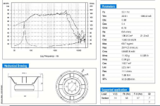
Seems this speaker dips to an alarming 3 ohms at the top end but is described as 8 ohms nominal.
I ran a very rough sim to see how it works. The 8.2R is just a modelling device for an 8 ohm tweeter I used here. The dotted lines are with the B&W original filter.
View attachment 1266598
View attachment 1266599
I found the shunt RC doesn't actually do much. The RC tank cuts breakup around 5kHz considerably. Replacing the 0.47R with 2.2 at the tweeter input improves impedance at the top, whilst reducing level 2dB.
I see I used 1.8R in the shunt, not your 1.5R, but that is no matter.
Make of it what you will. It is what it is. But definitely room for improvement IMO. 🙂
Best, Steve.
I see many posts around these speakers and 601 and various versions, but they always get hijacked by different model questions so very hard to deduce the solution options for DM602 S3 in particular.
Do you by any chance have the project files for DM602 S3 as pictured here? I am looking to perform the upgrade but would like to simulate changes to my preference.
Thank you
Hello All,
Can I change the subject on Crossover upgrade Focal Electra 906 or is necessary to open a new topic ?
I would be grateful if someone would post the original schematic because I couldn't find it. Does anyone modified original crossover for smooth response on bass?
I removed the midass from the speaker and I could barely see the components mentioned below, I don't have a photo of the back of the filter.
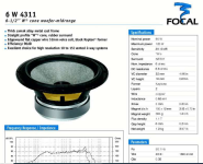
What I know is that the filter contains a large air coil, a smaller air coil, an iron core coil, 4.7 ohm /7 W 10% resistor, 10 ohm /10 W 10% resistor, 15 uF 63 Volt 10% bipolar capacitor, 12 uF capacitor, and between the two 4.7 uF capacitors is a 3.9 uF one. Midbass Focal 6W4351 and tweeter TC90TD5B titaniumdioxide.
I only have the parameters for the midbass in the attached photo.
Thank you.
Can I change the subject on Crossover upgrade Focal Electra 906 or is necessary to open a new topic ?
I would be grateful if someone would post the original schematic because I couldn't find it. Does anyone modified original crossover for smooth response on bass?
I removed the midass from the speaker and I could barely see the components mentioned below, I don't have a photo of the back of the filter.
What I know is that the filter contains a large air coil, a smaller air coil, an iron core coil, 4.7 ohm /7 W 10% resistor, 10 ohm /10 W 10% resistor, 15 uF 63 Volt 10% bipolar capacitor, 12 uF capacitor, and between the two 4.7 uF capacitors is a 3.9 uF one. Midbass Focal 6W4351 and tweeter TC90TD5B titaniumdioxide.
I only have the parameters for the midbass in the attached photo.
Thank you.
Attachments
I don't know the crossover but if you can pull it for a front and back photo, we might trace it and simulate it.
There are other methods you could use. For example, measure the system response and EQ the bass response as needed. Perhaps it's your room in any case which means that would be the correct way of approaching it. Not that it should make a difference, you can do it that way but do you really want to change the crossover for a problem that isn't with the speaker?
Alternatively you could measure the drive signal to each driver, however it's difficult to say what you would do with it until it's known why you'd have to resort to it.
Petross has provided this image so I've cross referenced the front and back so it can be traced.


It's a difference beetwen 10 J and 10 uF, because Focal work with Joules on cappacitors. You know kind of calculation, or îs the same?
You've made a mistake in your writing.This is a good way of controlling breakup at 5kHz in this case:
View attachment 1266028
It's called a tank notch, and with 1mH coil you'd want 1uF and 22R for 5kHz. Really changes the sound entirely!
The resistor is important because without it you'd get a dead short at high frequency with a shunt capacitor across the bass.
A "dead short at high frequency with a shunt capacitor across the bass" is what would occur if you omitted the resistor AND inductor
using a parallel Zobel R/C network.
However, the circuit shown uses only series components with the woofer, so such a statement is not correct.
PS.
A .068uF cap in series with a 22ohm resistor across a 1.5mH inductor is a very subtle and nearly meaningless adjustment.
Last edited:
Not bad if you want to deal with breakup though. It's a resonant circuit so it could pull the response right down.. dependent on damping, of course.

I think I was sort-of saying that to address breakup & nasty woofer HF, Zobel networks are a HIGHLY EFFECTIVE integral component.
( I would always choose them over anything that is even slightly resonant > including a suppressed null )
PS.
YES, the inductance of a voice coil and R/C is a form of resonant circuit.
( I would always choose them over anything that is even slightly resonant > including a suppressed null )
PS.
YES, the inductance of a voice coil and R/C is a form of resonant circuit.
Last edited:
I'd consider the impedance compensation too and sometimes I might even use it.. but you know, a little RC plus some L in the driver impedance... No, the resonant circuit will work as expected.. but there is an interesting difference.
Joe Rasmussen's Elsinore speakers use just this kind of circuit for the tweeter. It looks like first order but cuts like sixth order and has phase like third or fourth. These are sleeper circuits in that regard. Not the only way to do it, but they can save on parts and are adjustable.
Joe Rasmussen's Elsinore speakers use just this kind of circuit for the tweeter. It looks like first order but cuts like sixth order and has phase like third or fourth. These are sleeper circuits in that regard. Not the only way to do it, but they can save on parts and are adjustable.
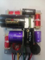
Today I replace capacitors and resitors in the filters. Sound în not bad but I need 200-400 houres of listening to be satisfied.First of all, thank you.
Recap with ClarityCap and an Jantzen Premium for 15 uF, it's a solution,without change The schematic of filter?
Attachments
Hello AllenB.
I replace 4 factory capacitors with ClarityCap values 12 uF, 4.7 uF, 3.9 uF, 4.7 uF. The 15 uF 63 V capacitor remained the same. After 300 hours of listening, I would like to improve the smoothness and clarity of the low bass or lower the bass response as low as possible, below the 50 Hz specifications.
Please help me with the filter diagram in the attachment and where I can intervene to improve the bass response as low and as smooth as possible.
Thank you.
The crossover does not affect the bass, so you cannot directly control it there. You can use the crossover to reduce the mids and treble, maybe this will have the same effect. You would start by increasing the woofer series inductor and increasing the tweeter series resistor.
Before this, I would try positioning the speaker better in the room since room modes have a significant influence. A good solution would be to configure a multi-sub setup. After this you might look at equalising the bass.

Before this, I would try positioning the speaker better in the room since room modes have a significant influence. A good solution would be to configure a multi-sub setup. After this you might look at equalising the bass.
- Home
- Loudspeakers
- Multi-Way
- Crossover mod surprising results