This is BS, one board works fine so the design is OK. It's not a very intelligent move to chuck a design because a part failed
Jan
There is no coming around that the impedance of the LF filter is falling toward zero at UHF. How will this affect class D amplifiers and their protection circuits?
My simulations show an impedance of 0,36 ohms at 500kHz. If the switching residue amplitude is 1V at this frequency that equals 2,8Amps.
We kind of proved this by installing a 2uH inductor.
Just my thoughts.
Have you looked at the Zout of that amp at 500kHz? Have you seen the components in its output filter?
Hint: is a C dead across the output. 0.36ohms will be invisible at 500kHz.
Jan
Hint: is a C dead across the output. 0.36ohms will be invisible at 500kHz.
Jan
Last edited:
Good! Then swap LF_C1 from the 'good' board and see what happens.
Jan
Done. Now the "bad" board works.
Tested the cap from the "bad" board on the good one, and the issue followed the cap.
Went and bought a pair of Jantzen 1uF caps to test with.
All of them have the same issue.
In other words, it's only the cap from the good board that "works".
This DIY forum contains amp designs like the Winfield's 100W DC-10MHz 1000V/us amplifier or the famous F5 without high frequency restriction (I think most diy F5 builds don't use a lowpass input stage or output stage. High frequency oscillation from 200kHz to 1MHz is possible (depends on design)). So we have to consider these designs. If this crossover is used without a proper protection on the outputstage and without a high frequency restriction, the amp will be damaged. And if the ouput has a proper protection, the protection curciut will pretent normal operation, as is the case of this threat.
I have to agree with Snickers and Amand, that this crossover has a really poor design. And in my oponion, all the hussle during improving/repairing and spendings are not worth the effort. I think the best way would be a new design.
I have to agree with Snickers and Amand, that this crossover has a really poor design. And in my oponion, all the hussle during improving/repairing and spendings are not worth the effort. I think the best way would be a new design.
In any case we now have logic proof that it is most probably the design. That's a worthwhile result, to be certain.
But be aware that with the class D design used here, the amp already has a cap shunting the output, as part of the output low pass. So it's unlikely that a cap load at 500kHz does anything, positive or negative.
I will now go into monitoring mode....
Jan
But be aware that with the class D design used here, the amp already has a cap shunting the output, as part of the output low pass. So it's unlikely that a cap load at 500kHz does anything, positive or negative.
I will now go into monitoring mode....
Jan
i was thinking of buying htm-12 for tvsound, not anymore lol.
the people behind these kits literally think they have world class designs, yet are unaware of such defects?
the people behind these kits literally think they have world class designs, yet are unaware of such defects?
This is the first time this kind of issue has come to light. Most amplifiers have no problem with the load occurring at ultrasonic frequencies well above the audio bandwidth and many designs employ a similar tank filter.
My suggestion would be to either remove LF C1 or better yet unsolder one leg and place a 4-10 Ohm 5-10W resistor in series with it (minimal change in frequency response) this prevents a pure capacitive load at ultrasonic frequencies.
The HTM-12 has a resistor in the circuit and will not exhibit a pure capacitive load like this.
It seems that some ICE-power modules have problems with this filter as there is also another Norwegian guy that experiences the same problem.
I am aware that class D amplifiers have a LC filter on the output, but I don't know the details about the ICE modules output or protection circuitry.
It seems like a 5 Ohm in series with LF C1 will be sufficient to cure the problem.
A 2uH in series with 2 ohm will give even higher impedance over 100kHz and will alter the frequency response less. Winding a ~2uH air coil is easy. About 15 rounds of 1mm enameld wire around a AA battery should be about 2uH.
This is BS, one board works fine so the design is OK. It's not a very intelligent move to chuck a design because a part failed
Jan
So only the faulty board has two capacitors connected in series between + and - input pins?
This is the first time this kind of issue has come to light. Most amplifiers have no problem with the load occurring at ultrasonic frequencies well above the audio bandwidth and many designs employ a similar tank filter
It is not allways a question about "works or doesn't work". One should have a bit more margin also. It is like powering a heating element with the amp at the same time as you power your speaker. It would work, but it is not hard to explain why it is not a brilliant idea.
It is like powering a heating element with the amp at the same time as you power your speaker.
It is nothing like that example.
If I design tires with an aggressive tread for forklifts and I test them on many different forklifts and rate them for speeds up to 20mph. Many people buy them and use them with their forklifts happily without issue. Then someone comes along and uses those tires on a forklift that at times spins them at an RPM equal to 200mph which results in vibration and causes the forklift shut down to protect itself. Is that issue the fault of the tires or poor forklift design?
Now I as a designer knew the aggressive tread would cause vibration at very high RPM but also knew this RPM would occur well above the normal operating speed of forklifts. I also know that many other designers have used a similar tread pattern on their tire designs without trouble. Is it my fault that unbeknownst a handful of forklifts use excessive RPM beyond what these tires were tested and rated for causing trouble on those models of forklift?
Certainly once this issue on certain models of forklift was brought to attention I would want to make sure a simple inexpensive fix allows the existing tires to be used and operate at the higher RPM with no issues. And would also take this new information into consideration on all future tire designs.
Well, we are dealing with a filter that does short the amplifier. And you are telling me that by using it with an amplifier that is not built to be shorted, you are not using the product correctly?
I'm saying the crossover was designed for a specific operating bandwidth and irregular behavior from a handful of amplifiers that just happen to generate a signal well outside that bandwidth isn't something that was expected when the crossover was designed.
the people behind these kits literally think they have world class designs, yet are unaware of such defects?
Think the Volts are world class designs? Defects? 🙄
********************
The same type of crossover circuit design is used in completed speakers sold by many companies. And the same type of crossover circuit design is also used in speaker kits sold by other companies. A very popular one is the Overnight Sensation that has probably been built 10,000 times in the past 10 years. A large number of Volt speaker kits have been built over the years as well. No issues at all so far. Zero.
One person has one channel from one amp go into protection mode and some people want to blame a speaker that has never had a problem with the other thousands of amp channels they've been hooked up to? Really?
Let's use common sense. Are the other thousands of amplifier channels just lucky not to go into protection mode with the same speaker? Or could it be a funky amp that couldn't deal with one of it's two channels being hooked up to a common crossover design?
The crossover design is fine. If it was causing issues someone would have contacted me in the past 6 years. Out of thousands, one or two funky amplifier channels going into protection mode does not qualify as a crossover defect. It means someone found one channel of an amp that might be overly sensitive.
It sounds like the amp manufacturer needs to post a note saying: "99.8% of amplifiers can power this common type of crossover, but our amp might not be able to because of our inadequate filtering."
The root cause of this discussions is that nobody is really interested in debugging and diagnosing an issue.
Most here are only interested in throwing up their own fav design, part, method. That is much easier than actually thinking about it.
That is the reason that these threads quickly degenerate into a trainwreck and nobody knows what it is about anymore. The poor guy who asked the question in the first place is inundated with irrelevant stuff and gets completely lost.
Diyaudio used to be about helping each other, instead of promoting yourself and your fav product.
Jan
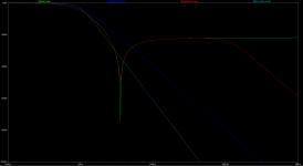
Here are some different solutions.
1) If you remove LF_C1, you will get a 12dB/octave low pass (blue plot)
2) If you put a 2µH 2Ohm coil in series with LF_C1, you will get a quiet similar curve with higher impedance above 100kHz. (red plot)
3) Is a 3rd order Butterworth lowpass filter with f(r)=1kHz. (I don't like third order lowpass filters for 2way crossovers, cause the inductance of the woofer voice coil is higher than the inductance of the second filter coil, and in my opinion, the second filter coil is mostly useless) (cyan plot)
The design of this crossover got it's benefit with a steeper rolloff between lp transition frequency and parallel transition frequency(green plot). But why should you burden your woofer with frequencys above 5kHz?
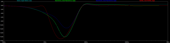
The second plot shows the complete crossover designs
original design (cyan)
2µ 2Ohm design (green)
without LF_C1 (blue)
3rd order lowpass (red)
I think, that solution 2) (additional coil) is worth a try, cause it got a similar characteristic without the high frequency problems.
1) If you remove LF_C1, you will get a 12dB/octave low pass (blue plot)
2) If you put a 2µH 2Ohm coil in series with LF_C1, you will get a quiet similar curve with higher impedance above 100kHz. (red plot)
3) Is a 3rd order Butterworth lowpass filter with f(r)=1kHz. (I don't like third order lowpass filters for 2way crossovers, cause the inductance of the woofer voice coil is higher than the inductance of the second filter coil, and in my opinion, the second filter coil is mostly useless) (cyan plot)
The design of this crossover got it's benefit with a steeper rolloff between lp transition frequency and parallel transition frequency(green plot). But why should you burden your woofer with frequencys above 5kHz?
The second plot shows the complete crossover designs
original design (cyan)
2µ 2Ohm design (green)
without LF_C1 (blue)
3rd order lowpass (red)
I think, that solution 2) (additional coil) is worth a try, cause it got a similar characteristic without the high frequency problems.
Attachments
The root cause of this discussions is that nobody is really interested in debugging and diagnosing an issue.
Most here are only interested in throwing up their own fav design, part, method. That is much easier than actually thinking about it.
That is the reason that these threads quickly degenerate into a trainwreck and nobody knows what it is about anymore. The poor guy who asked the question in the first place is inundated with irrelevant stuff and gets completely lost.
Diyaudio used to be about helping each other, instead of promoting yourself and your fav product.
Jan
The guy who started this thread has received some serious help on a Norwegian forum.
In order to fix this, one should have access to the drivers and enclosure, and start over from scratch.
Those with an insatiable curiosity would proceed to determine the minimum resistance required to stabilize that amplifier/network pairing.
It may be as low as 0.5 ohms added inline with the 1uF capacitor ( considering some of the possible reasons one network actually works well enough with this amp ).
Measuring the ESR of that single 1uF capacitor that didn't upset the amplifier ( of the 4 tried in circuit ) would be illuminating.
Just saying.

🙂
It may be as low as 0.5 ohms added inline with the 1uF capacitor ( considering some of the possible reasons one network actually works well enough with this amp ).
Measuring the ESR of that single 1uF capacitor that didn't upset the amplifier ( of the 4 tried in circuit ) would be illuminating.
Just saying.
🙂
Last edited:
The root cause of this discussions is that nobody is really interested in debugging and diagnosing an issue.
Most here are only interested in throwing up their own fav design, part, method. That is much easier than actually thinking about it.
That is the reason that these threads quickly degenerate into a trainwreck and nobody knows what it is about anymore. The poor guy who asked the question in the first place is inundated with irrelevant stuff and gets completely lost.
Diyaudio used to be about helping each other, instead of promoting yourself and your fav product.
Jan
Unfair.
While you had one approach helping, I had another.
1. I reverse engineered the filter based on the PCB layout and created a scematic. How is that not helpful?
2. I presented the hypothese that the 500kHz switching residue from the class D amp might be the problem and suggested a fix for this with the 2uH inductor + 2 ohm resistor. (It even worked). How is that not helpful?
- Status
- Not open for further replies.
- Home
- Loudspeakers
- Multi-Way
- Crossover makes amp go into protection mode