Desoldering braid, or a desoldering pump when it is leaded solder (lead-free solder tends to clog the pump).
Defo
If the amp goes into protection mode just after connecting the crossover, there must be a major (short) problem. What I meant … did You try the same speaker with the same crossover or did You swap them ? Do you get sound at low volume for seconds or does it trigger protection right away ? It shouldn't trigger protection at low volume. Perhaps the amp is faulty and not the crossover.
If the amp goes into protection mode just after connecting the crossover, there must be a major (short) problem. What I meant … did You try the same speaker with the same crossover or did You swap them ? Do you get sound at low volume for seconds or does it trigger protection right away ? It shouldn't trigger protection at low volume. Perhaps the amp is faulty and not the crossover.
Defo
If the amp goes into protection mode just after connecting the crossover, there must be a major (short) problem. What I meant … did You try the same speaker with the same crossover or did You swap them ? Do you get sound at low volume for seconds or does it trigger protection right away ? It shouldn't trigger protection at low volume. Perhaps the amp is faulty and not the crossover.
I get sound before it goes into protection for about 6 seconds. Then normal operation with sound for a second or so before it goes into protection again. Pretty weird... Amp works perfectly fine with all other speakers I've tried previously.
The fact that the crossover actually "functions" (i.e I get sound before the amp goes into protection) makes this issue even more puzzling to me.. How can the XO both function and not function? 😕
That will depend on what fault the protection system is tripping on.
Voltage, current, temperature.
And each one could be cause by different, or multiple issues.
A 10 litre bucket will hold 9.9 litres all night and day.
Pour another litre in and it will fail and over flow the extra 0.9 litres.
Since one crossover works, I would suggest swapping one part at a time between good and bad boards.
Use a bit of tape to mark the parts on the failing unit to help you keep track of what you have and haven't changed.
I'd also write a list of all the parts, then put a line next to it when you change that part.
Once a single part is swapped, retest both crossovers.
That will help eliminate any issues with assembly.
But the photos you've shown look really neat.
Time consuming and a pain in the ..... but it means you don't need test gear or a bunch of new parts.
Could you post a photo of the top and bottom sides with both units next to each other ?
I wonder if one part is not in the right spot.
Perhaps the short is elsewhere. The crossover functions because there is nothing wrong with it.....but you may have a parallel short
Perhaps the short is elsewhere. The crossover functions because
there is nothing wrong with it.....but you may have a parallel short
Have the crossovers been swapped between channels, with all else remaining exactly the same?
If so, did the problem change channels, along with the (supposedly bad) crossover?
Last edited:
There was a time when I had zip-tied down a coil, and the ratcheting of the part to the board allowed the urethane on 2 places of the coil to rub and short out. It is possible that the coil in the tweeter spot might be doing this. This could look like a short to the amp.
Later,
Wolf
This might be a point. In this case, each coil on itself would still measure 0.8 ohms and seem OK, but the short wrecks the operation. The test for this could be a resistance measurement between the end of one coild and the end of another coil.
Jan
Since one crossover works, I would suggest swapping one part at a time between good and bad boards.
The components are hot glued to the board 🙄 It's probably doable cutting the glue, but it will be quite an undertaking. I guess this might be the last resort.
Have the crossovers been swapped between channels, with all else remaining exactly the same?
If so, did the problem change channels, along with the (supposedly bad) crossover?
Swapping just the crossovers while having everything else exactly the same - the problem does indeed change channels along with the bad crossover.
This might be a point. In this case, each coil on itself would still measure 0.8 ohms and seem OK, but the short wrecks the operation. The test for this could be a resistance measurement between the end of one coild and the end of another coil.
Jan
Tried measuring now. Still get 0.8 ohms for both boards.
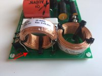
Just to make sure, I've attached pics of where I measured:
Attachments

Last edited:
Eureka! Disconnected the big cap for the woofer and now all is good! This begs the question tho, what is wrong with the cap?
An internal short in a coil will be hard/impossible to see normally - trying to run it at high power may provoke visible arcing, but may also damage the amp and speakers.
Close visual inspection (ie with a magnifier) might throw something up (perhaps one coil
got scrapped by a sharp metal object?).
There might be an intermittent capacitor or solder joint that only shows up with higher voltages/currents than a multimeter will provide.
[ postings overlapped! Good to hear its figured out now - the cap is either shorted, open or intermittent, whatever it just needs replacing with a non-polar equivalent ]
We don't know yet something is wrong with the cap.
A quick test would be to temporarily fix the 'good' cap to the 'bad' board, to get confirmation it is the cap and not the associated wiring.
Jan
A quick test would be to temporarily fix the 'good' cap to the 'bad' board, to get confirmation it is the cap and not the associated wiring.
Jan
Last edited:
Eureka! Disconnected the big cap for the woofer and now all is good! This begs the question tho, what is wrong with the cap?
My guess is an intermittent short in the cap, sensitive to either vibration or temperature. Electrically, there are two conductive "plates", separated by a dielectric material. Sometimes a metal film is deposited directly to the dielectric, or a layer of metal foil alternates with the dielectric film. To save space this is wound in a tight little bundle. One plate could short against the other if there is physical damage or a defect.
Once the short circuit begins there will be a sudden spike in current through the cap, which would generate heat. This might be enough to maintain the short circuit until it cools down, or the short occurs frequently enough that the protection circuit is retriggered.
The big cap for the woofer??? Isn't that for the tweeter? You could be driving the tweeter with full music signal... a sure way to fry it.
I would do as Jan said. Very good idea.
I would do as Jan said. Very good idea.
We don't know yet something is wrong with the cap.
A quick test would be to temporarily fix the 'good' cap to the 'bad' board, to get confirmation it is the cap and not the associated wiring.
Jan
Just did this, and it's not the cap 🙁 Now I really have no clue...
Well you've swapped one cap.
Now keep going with the other parts.
One at a time, then test both crossovers.
Now keep going with the other parts.
One at a time, then test both crossovers.
Well you've swapped one cap.
Now keep going with the other parts.
One at a time, then test both crossovers.
Isn't it possible to deduce something from the fact that removing the big woofer cap fixes the issue?
If we knew what the circuit was, then yes. Since it's of proprietary nature, we don't know this information.
Later,
Wolf
Later,
Wolf
If we knew what the circuit was, then yes. Since it's of proprietary nature, we don't know this information.
Later,
Wolf
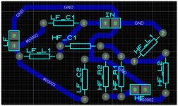
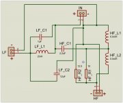
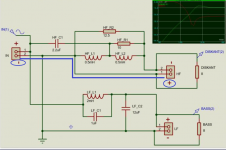
See attached pics. Pretty sure its correct.
First is board layout.
Second is schematic based on board layout.
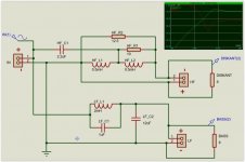
Third is re-arranged to make it easier to read.
Hope that brings some value!
Attachments
Last edited:
- Status
- Not open for further replies.
- Home
- Loudspeakers
- Multi-Way
- Crossover makes amp go into protection mode