To me, it boils down to class A/B having a mild but stable amplification basin at lo levels, while lo level amplification basin of class B is deeper and less stable, as electron valves age.
My description of bipolar crossover was maybe a bit too glossed over above (post 20).
Bipolars have near constant Beta (current gain) outside of the threshold voltage region. And VAS stages provide complementary current drives. So the crossover region would have bad "Beta doubling" if it were not for the standard differential base voltage limiting (bias control) circuit and some Beta variation within the threshold region. Complex in detail, but well understood (see Self or Cordell books). High N Fdbk used to flatten out the wrinkles in the crossover region.
From a tube design perspective, SS bipolar amps operate in very near class B typically, since their Beta is nearly constant over most of the operating region. Mosfets typically operate more in class aB due to their mostly square law operation. High N Fdbk fixes the gm variation.
Of course class A is available for either, but is power hungry.
-------
Class B grid 1 drive for tubes does not make good sense due to the near square law tube operating mode causing bad gm variation. (the V shaped gm curve) Unless high level N Fdbk is used with it.
Class B, Grid2 drive, has less gm variation (due to 3/2 power law), but certainly is not constant. Still needs N Fdbk. Does make for efficient operation.
Class B, Crazy Drive or Twin Drive, does make good sense in near class B since it does maintain constant gm throughout the operating region. With good efficiency.
George (Tubelab) is even considering class G (or H) for efficiency, with multiple B+ levels. This will introduce numerous crossover points. Cathode follower mode used to isolate the output from shifting B+ levels.
..
Last edited:
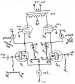
Here is another approach to avoiding crossover distortion in class B (from an old thread).
Start with a low voltage, high current class A P-P stage, and strip off half of the output waveform before driving the class B cascode stage above it with current drives.
The gyrators are adjusted to the same threshold voltage (could be done more elegantly with matched transistors and the same V reference), so automatically must extract exactly half of the current supplied by the bottom CCS tail. Ensuring exact 180 degree drive for each tube up top. Current drive ensures no gm variation effects from up top. Could be triodes up top to avoid screen current distortion.
Attachments
Last edited:
Self's problem is, that "optimum" for class B highly depends on temperature, and since his "blameless" transistors are biased by voltage depending on temperature of the heatsink that is far from temperatures of transistor dies, it is never optimal, and transistor amps designed by "blameless" OpAmp topology as the result sound worse than tube amps (one of reasons).
In order to overcome this problem Douglas built an amp with a PCB full of 5532 chips in parallel. ;-)
It may look like one tube where each opamp represents a gap between wires of the control grid. 🙂
Well, Self had several solutions to the issue the most interesting of which I thought was the crossover displacement idea. He's definitely a methodical and out-of-the-box thinker and I'm glad I read his book.
Crossover displacement idea.
That's pretty much the same as limited class A + class C. Where the class A gives up, the class C takes over. I think Anatoly has already done some work with that. But now you get two crossover points, away from zero at least.
One could also just use a class A P-P pentode stage with standard center tapped OT. Then use a big Mosfet to control the B+ level to the center tap to follow the envelope of the signal waveform. Then the class A amp operates near maximum possible swing all the time for best efficiency (with large current variation, but tube plates always pulled down to low voltage). Of course, now the Mosfet gets real hot instead of the tubes. Could use a class D amplifier (just half of it actually) in place of the Mosfet for efficient operation. Not a bad idea I think.
Last edited:
This is different than the crossover displacement that Self describes. Do you have Self's book? He injects a current into the output node of the amplifier that just moves the crossover point away from the low signal operation region. There is still only one crossover region but it is shifted so that it will only occur at higher volume levels, and it has already been minimized as much as possible. Obviously, this comes with some efficiency compromises but not nearly as much efficiency compromise as going class-AB or class-A.
I'd love to adapt this to a tube amp but I don't think it can be done quite so simply since the output transformer screws things up but maybe there is a way to do it elegantly and simply. Any ideas, circuit maestro?
I'd love to adapt this to a tube amp but I don't think it can be done quite so simply since the output transformer screws things up but maybe there is a way to do it elegantly and simply. Any ideas, circuit maestro?
I do have Self's book(s). Basically just a V offset added in the signal so it centers (idle) around something other than the transistor crossover. (actually a V offset put in the signal, then a compensating V offset taken back out of the output, Self used a current source pulling on the output)
For the tube version, you need an offset V added to one grid side and subtracted from the other side. This is similar to just biasing the two P-P tubes differently. The OT already takes out the DC offset from the output. To fix the OT current balance then, put a CCS circuit on the low current side to even up the idle currents. I think.... Good idea to simulate this before burning something up.
(or get George to try it.... he likes breathing refreshing smoke in the morning I think 🙂 )
Last edited:
To me, an amplifier with bias set-up by cathode resistors is Class A or A/B, for example a Telefunken 10W 2xEL86 movie sound amplifier, while one with negative control grid voltage is Class B, for example a Dynacord 2x80W PublicAdress amplifier with 2x2xEL34.
Actually, you've described 'cathode bias' or 'automatic bias' (resistor between cathode and ground), versus 'fixed bias' (negative voltage applied to grid, cathode at ground potential). A class A or class AB amplifier can have either cathode bias or fixed bias. The type of bias is separate from the class of operation.
The use of fixed bias does *not* automatically make an amp operate in class B. Far from it. The Dynaco Stereo 70 is an example of a very common audio amplifier with a fixed bias, class AB output stage.
It's certainly possible to make a fixed bias amp run in class A.
--
Well, I think it would be cool to implement a crossover displacement tube amp. I might spend some time thinking this through this weekend.
However, it seems to me that the main advantage of class-B operation might be wiped out in a crossover displacement scheme anyway. The main advantage of class-B is being able to use a smaller tube (capable of only small idle current) to get big output power. In crossover displacement, one tube is going to have to idle at a higher current than the other. Would it still be low enough to be worth it? My gut says probably not but I need to run the numbers. Maybe things are better than I think.
So what would be better, class AB or class B with crossover displacement? This seems like a very interesting line of inquiry for some experiments. I think I might move on to this after my current line of experimentation. I have a pair of push-pull transformers that might be good for this.
All of this is kind of academic to me anyway because in general I like higher idle currents in the output devices for the low Zout that it offers. Tube amps tend to be too high in output impedance for my liking so anything that tends to drive that up further has to have some other huge benefit. If I am building a tube amp I have already decided that efficiency is not my top priority.
Yeah, I think one will want to displace the crossover by the same amount that the class AB would already do, to get the irregularity out of the easy listening level. So rather questionable as to merit for tubes. Class AB for bipolars is not really a good option though. The CCS will consume power besides. No free ride.
I myself would just use some bigger cheapo TV tubes and let it run a bit hotter in class AB. Or run it in Crazy/Twin Drive for efficiency and hopefully with low enough distortion at low idle current.
The variable B+ for a class A amplifier approach, using a Mosfet B+ regulator driven to instantaneous signal max (B+) requirement seems like an interesting and do-able idea. It doesn't save any energy over full class A, just transfers most of the heat to the big Mosfet. But if it works satisfactorily, one could venture further and replace the Mosfet with a class D amplifier module driving an OT backwards to set the dynamic B+ for the class A amp. More tricky for sure, especially bandwidth of the dynamic B+. Some guard band of extra voltage needed likely, unless the signal can be delayed slightly to the class A amp.
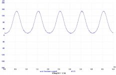
To check the crossover or not in a p-p the way is very easy.
Just put in series to the cathode to ground a 1 ohm 1watt resistor for each power tube.
Also for cathode bias.
In this way you can monitor exactly twhat happen on output stage.
In other my thread I sent two diagrams about this check, now I post it again
In fig. 10 you can find a voltage across 1 ohm with 55 mA of bias current on a p-p of KT120, fixed bias, pentode connection
The cycle is complete so we are in class A, the power delivered to a load of 8 ohms is about 10 watt rmas.
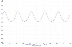
In fig. 11 there is a test where the bias is at 90 mA, in this case, always class A, we are around 32 watts rms.
If you lower the bias you can see that one semi-wave is gone, tend to zero with the bias at 0 mA.
I am trying to read carefully the thread but due my poor english I have understood just some concept.
But I can't understand we have to use the class B in a p-p; there is no reason .
The tubes give us the possibility to set the idle current for a wide range of value; there is a great diffference with ss because we have to care about dissipation and the area we must use or we destroy the stuff.
With the tube, until we reach the maximum ratings ( and a good ventilation, of course) , we can manage the performances because, p.e., if we increase the bias current we lower the Rp of the tubes so the coupling with O.T. will be better.
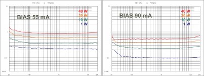
Look at fig. 6 where we have the same circuit with two different bias; the THD vs freq, for different power, is better at higher bias.
Of course the life of the tubes become shorter but, in this situation, normally the sound is better
Walter
Just put in series to the cathode to ground a 1 ohm 1watt resistor for each power tube.
Also for cathode bias.
In this way you can monitor exactly twhat happen on output stage.
In other my thread I sent two diagrams about this check, now I post it again
In fig. 10 you can find a voltage across 1 ohm with 55 mA of bias current on a p-p of KT120, fixed bias, pentode connection
The cycle is complete so we are in class A, the power delivered to a load of 8 ohms is about 10 watt rmas.
In fig. 11 there is a test where the bias is at 90 mA, in this case, always class A, we are around 32 watts rms.
If you lower the bias you can see that one semi-wave is gone, tend to zero with the bias at 0 mA.
I am trying to read carefully the thread but due my poor english I have understood just some concept.
But I can't understand we have to use the class B in a p-p; there is no reason .
The tubes give us the possibility to set the idle current for a wide range of value; there is a great diffference with ss because we have to care about dissipation and the area we must use or we destroy the stuff.
With the tube, until we reach the maximum ratings ( and a good ventilation, of course) , we can manage the performances because, p.e., if we increase the bias current we lower the Rp of the tubes so the coupling with O.T. will be better.
Look at fig. 6 where we have the same circuit with two different bias; the THD vs freq, for different power, is better at higher bias.
Of course the life of the tubes become shorter but, in this situation, normally the sound is better
Walter
Attachments
Last edited:
Nice show, Walter! But in the following plot
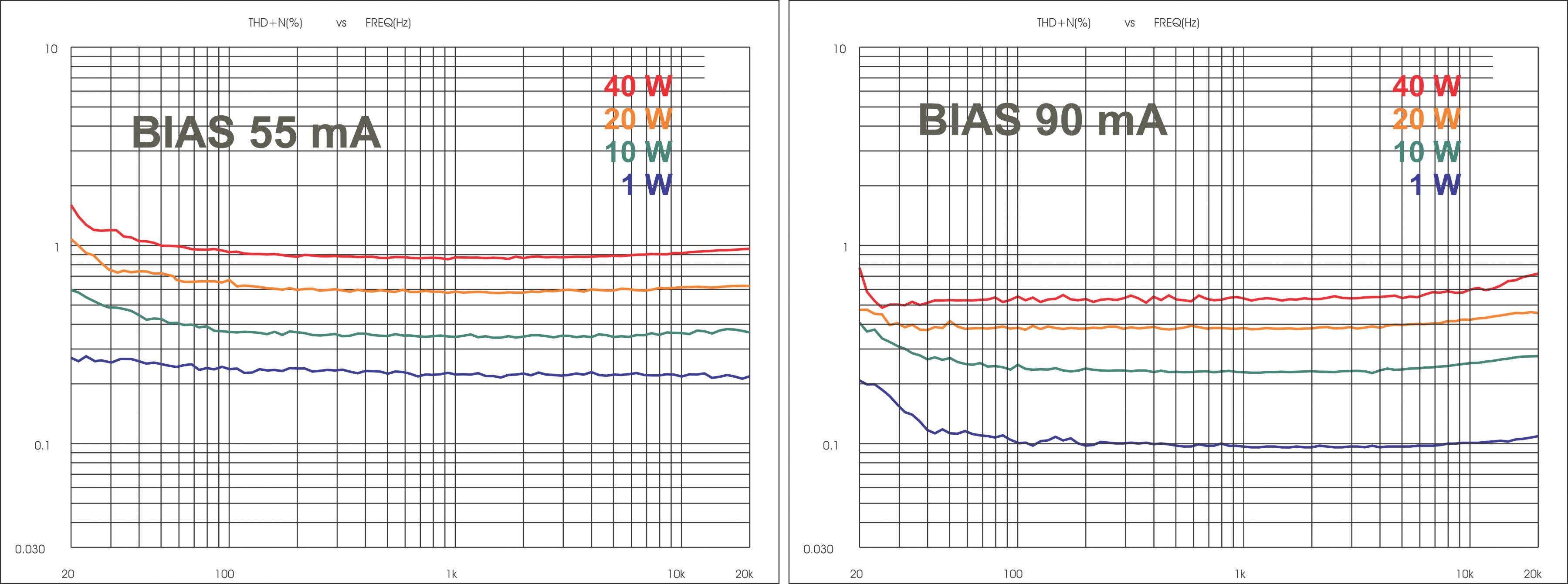
by thee, there is no crossover distortion visible, because distortion becomes lower, as output power is lowered. But it is THD, so we do not know, if each harmonic obeys the monotonic law.
Class B has higher maximum current but mostly supply voltage than A/B. EL34 can be used with 800V=. Make no mistake, tho you are gonna survive it.
Another reason the transistor guys fret "crossover" is because they "can" and thus do idle way-way cold.
A tranny amp of 20A peak may be idled at 0.1A, a 200:1 range.
Tale a tube amp of 200mA peak. Would you idle it at 1mA?? No, in part because the drive voltage requirement to get from 1mA to 200mA would be enormous. Drive is easier with like 50mA idle. Now only a 4:1 range from idle to peak.
The most extreme Suggested Condition I know (discounting battery-amps which have special bias needs) is 7189. Book says to idle at 15mA/pair (7.5mA each) for what must be 145mA peak. 20:1 peak:idle ratio. Extreme for a tube, hot for a transistor amp. And my ears like this condition working considerable hotter than 15mA.
Also you can *approximate* many tubes' Gm/Ia curve as square-root. Gm at 50mA is roughly half the Gm at 200mA. Therefore the total Gm is fairly constant from idle to peak. Not exact, and the "optimum" idle is rarely just 1/4. But there's no wicked kinks in the curves. Anywhere near here will work smooth.
Some very interesting posts and ideas here - many thanks to those concerned! Hopefully some ideas may be pursued and elaborated on?
About 15 years ago, I did a paper design of a basically-transistor amp which used triodes to create a softer crossover region. Unfortunately, I didn't get round to building it, and I've lost the schematic (along with a few zillion brain cells, so there's little chance of my resurrecting it - it was fairly complex, as you can imagine).
About 15 years ago, I did a paper design of a basically-transistor amp which used triodes to create a softer crossover region. Unfortunately, I didn't get round to building it, and I've lost the schematic (along with a few zillion brain cells, so there's little chance of my resurrecting it - it was fairly complex, as you can imagine).
Some very interesting posts and ideas here - many thanks to those concerned! Hopefully some ideas may be pursued and elaborated on?
About 15 years ago, I did a paper design of a basically-transistor amp which used triodes to create a softer crossover region. Unfortunately, I didn't get round to building it, and I've lost the schematic (along with a few zillion brain cells, so there's little chance of my resurrecting it - it was fairly complex, as you can imagine).
A simple idea would be: if one wants to do a class AB amp with no cross-over distortion he could just use tubes and forget about it. 😀
With sweep beam power tubes one can get high power with relatively low plate dissipation. Over 100W RMS with low THD are possible with a pair of tubes rated for 25-30W max plate dissipation.
to Grasso
the diagram show only the reason why in a p-p you can set different bias current.
The use of strange tubes to reach big power with the risk to have crossover distortion, in my opinion, is not logical.
The main reason is that in a normal room the medium power we use is around 2 watts, with some peaks of course.
So we are using just a little parts of grid voltage through the load line close to point of bias.
If the bias point is close to 0 mA, we can see that the wave is 180 ° instead 360° and distorted because in that region the linearity is very poor.
In my opionin the trouble, in a p-p are, resides in other fields.
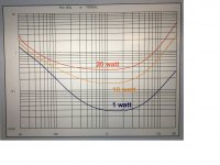
In attach a test THD vs Freq of a commercial tube amp, class A, KT88 triode connection.
Thre different power
Look at the low frequency and high frequency.
Walter
the diagram show only the reason why in a p-p you can set different bias current.
The use of strange tubes to reach big power with the risk to have crossover distortion, in my opinion, is not logical.
The main reason is that in a normal room the medium power we use is around 2 watts, with some peaks of course.
So we are using just a little parts of grid voltage through the load line close to point of bias.
If the bias point is close to 0 mA, we can see that the wave is 180 ° instead 360° and distorted because in that region the linearity is very poor.
In my opionin the trouble, in a p-p are, resides in other fields.
In attach a test THD vs Freq of a commercial tube amp, class A, KT88 triode connection.
Thre different power
Look at the low frequency and high frequency.
Walter
Attachments
The use of strange tubes to reach big power with the risk to have crossover distortion, in my opinion, is not logical.
Sorry Walter but sweep pentodes are not strange tubes they are simply much better than current production crap....😀
They can give more power because of the powerful heater and larger cathode area. Nothing strange....
I will be happy to measure an amp with these tube under our test procedure that are the most complete available (at my lab or at Audioreview lab)
If anyone has one ready I can arrange a spedition
Preferable within Europe
I will continue to define those tubes as "strange". 🙂
Walter
If anyone has one ready I can arrange a spedition
Preferable within Europe
I will continue to define those tubes as "strange". 🙂
Walter
I will be happy to measure an amp with these tube under our test procedure that are the most complete available (at my lab or at Audioreview lab)
If anyone has one ready I can arrange a spedition
Preferable within Europe
I will continue to define those tubes as "strange". 🙂
Walter
I' ll come back to Italy in August. I can bring the 6HF5's that are rated 28W. I have 4 new General Electric and slightly used pair of RCA's.
At 520V/50mA with 3.2K plate-to-plate they should make about 125W minus transformer loss. So it will be about 115W with 0.3 dB power loss.
- Status
- Not open for further replies.
- Home
- Amplifiers
- Tubes / Valves
- Crossover Distortion in Tube Class AB Amplifiers