Haha, I think me trying to understand where I'm making mistakes is part of that learning process ��. Thankful to everyone that is helping guys like me out there.
Thomas Edison once told his employer: "No sir, I have not made a successful light bulb. But I have discovered a great many ways NOT to make one."
We all learn by our mistakes.
Okay one final point on my current tracking scheme...
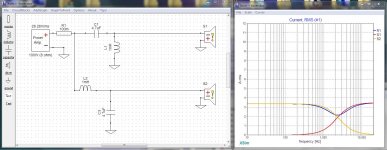
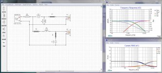
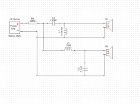
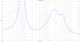
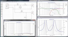
The first thumbnail shows a relatively high efficiency crossover, almost all of the current flowing goes through the speakers. In fact the current traces the speaker currents almost exactly.
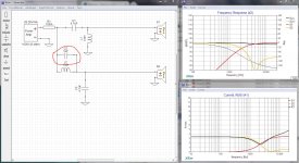
Now lets add some inefficiency and see what happens... The second thumbnial shows a common error that some "experts" actually advocate as a form of baffle step compensation. Notice that the frequency response curve is altered only very slightly... but look how the overall current graph (R1) gets separated from the driver's current. That extra current is going someplace... In fact the new capacitor forms a nearly dead short with C3 and the current just races. I find this much more informative than the impedance chart XSim opens by default.
There, done... now you guys can get on with your design...
The first thumbnail shows a relatively high efficiency crossover, almost all of the current flowing goes through the speakers. In fact the current traces the speaker currents almost exactly.
Now lets add some inefficiency and see what happens... The second thumbnial shows a common error that some "experts" actually advocate as a form of baffle step compensation. Notice that the frequency response curve is altered only very slightly... but look how the overall current graph (R1) gets separated from the driver's current. That extra current is going someplace... In fact the new capacitor forms a nearly dead short with C3 and the current just races. I find this much more informative than the impedance chart XSim opens by default.
There, done... now you guys can get on with your design...
Attachments
Last edited:
Among consumers I suppose. That leaves professionals and hobbyists.. more than a few of those around here 😉with exactly matching output and input impedances went right out the window with solid state amplifiers and Impedance Bridging sometime back in the 70s ... but we still see it today.
Eg: Unbalanced vs balanced interconnects. The consumers get the unbalanced and are led to believe that it is ideal.
Among consumers I suppose. That leaves professionals and hobbyists.. more than a few of those around here 😉
Even in pro-audio precise impedance matching is no longer a reasonable goal. Bridging, where a low impedance output feeds a higher impedance input took away all need for it in all areas of electronics, not just audio.
One of the reasons we need to be careful about amplifier current is that with impedance bridging many amps reach damping factors of 100 or more. That amounts to a .08 ohm output feeding our 8 ohm speakers. But realistic design limits dictate that with the amount of feedback needed to accomplish that kind of damping factor, the amp is very unlikely to actually survive it.. at 100 watts we're asking it for 3.5 amps, but there is no reason to expect it to survive 350 amps even for a very short burst.
I was just looking at these two drivers:
FaitalPRO 5FE120 5": FaitalPRO 5FE120 5" Professional Midbass Midrange Woofer 8 Ohm
Dayton Audio TD20F-4 3/4" Soft Dome: Dayton Audio TD20F-4 3/4" Soft Dome Neodymium Tweeter 4 Ohm
The loud 5" 90dB midbass, unusually, looks like a closed box 7L driver.
But impressively flat.
The tweeter is also 90dB. A lot of the impedance problems must stem from having to run the tweeter almost flat out. Hence no impedance raising resistors allowed. Which you'd normally do like this:
Peerless HDS PPB 830860
Everything would become easier with a louder tweeter. Maybe SB Acoustics. Maybe some sort of horn or waveguide design.
The tweeter is also 90dB. A lot of the impedance problems must stem from having to run the tweeter almost flat out. Hence no impedance raising resistors allowed.
Naaa ... he had a mistake in his crossover design.
I accept that some think in absolute terms and some see the bigger picture. We can tell the difference.. It's never not reasonable because it works for all cases, including Rs=0. If you brutally prune the skillset, you discriminate against the high Rs and current amp builders.impedance matching is no longer a reasonable goal. Bridging, where a low impedance output feeds a higher impedance input took away all need for it
Not in engineering. Impedance matching won't go away.in all areas of electronics, not just audio.
Another way to do this is to look at impedance. That works for all cases.about amplifier current is that with impedance bridging many amps reach damping factors
Just want to say kudos to Mr Blake - you have given an outstanding and easy to understand tutorial on some of the electrical fundamentals of xo's. I have not seen it explained like this or this well anywhere else including Dickason in his Loudspeaker Design Cookbook or Alden in Speaker building 201.
I almost want to recommend that his posts #'s 7, 9 and 22 get stickied somewhere.
Well done sir.
I almost want to recommend that his posts #'s 7, 9 and 22 get stickied somewhere.
Well done sir.
There is a member contribution sticky - Favorite Threads and Posts in "Loudspeakers"I almost want to recommend that his posts #'s 7, 9 and 22 get stickied somewhere.
Just want to say kudos to Mr Blake
Blush
Thanks. Just sharing what I know, hoping I'm right.
Not in engineering. Impedance matching won't go away.
To the best of my knowledge the only place where impedance matching remains a valid discipline is in antenna design, where a more or less accurate match is needed to ensure no returned energy on feedlines. But in audio and digital the go-to method is impedance bridging.
Hey guys, I have made another design trying to follow what I understood from the discussion. Can y'all have a look?
This time I am using a different tweeter, Dayton ND25FA and the same woofer Faital Pro 5Fe120. Hoping this one is a better design than the previous one.
This time I am using a different tweeter, Dayton ND25FA and the same woofer Faital Pro 5Fe120. Hoping this one is a better design than the previous one.
Attachments
-
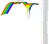
 Project 2.ii (Dayton ND25FA and Faital Pro 5Fe120) Polar Chart.png37.7 KB · Views: 139
 -
 Project 2.ii (Dayton ND25FA and Faital Pro 5Fe120) Directivity (hor).png56.2 KB · Views: 128
 -
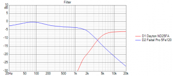 Project 2.ii (Dayton ND25FA and Faital Pro 5Fe120) Filter.png17.4 KB · Views: 127
 -
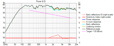 Project 2.ii (Dayton ND25FA and Faital Pro 5Fe120) Power+DI.png28.1 KB · Views: 177
 -
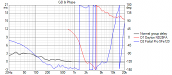 Project 2.ii (Dayton ND25FA and Faital Pro 5Fe120) GD+Phase.png24.7 KB · Views: 177
 -
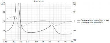 Project 2.ii (Dayton ND25FA and Faital Pro 5Fe120) Impedance.png22 KB · Views: 182
 -
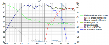 Project 2.ii (Dayton ND25FA and Faital Pro 5Fe120) SPL.png35.9 KB · Views: 192
 -
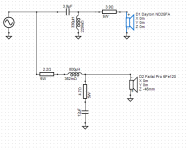 Project 2.ii (Dayton ND25FA and Faital Pro 5Fe120) Circuit.png15.6 KB · Views: 187
Okay... looking a lot better... Just a couple of tips...
1) If you take the series resistor out of the woofer chain (2,2 ohms) you will get about an extra 6db sensitivity (output) from the woofer. Also there's no way a 5 watt resistor is going to last in that location, with any amp beyond about 10 watts.
2) After #1, you can reduce the resistor in series with the tweeter to match the levels up.
3) It really isn't a big deal, but when necessary I usually reverse the tweeter polarity. This because it's a lot easier to get at the tweeter and flip the wires later, if you have to.
4) If you get rid of the 4.7 ohm resistor going to the cap in your woofer chain, you can adjust the capacitor's value to give you essentially the same result.
5) You may want to increase the value of the coil going to ground in your tweeter chain. It's still pulling quite a bit of current.
TIP... coils and caps can waste energy as current to ground but resistors waste it as heat.
This is a big improvement over your first attempt.
I've attached a thumbnail of your design in XSim, with a few adjustments... you may want to try them in your design. The lines through the resistors mean they are shorted and would not be included in the final design. (I didn't use the exact driver specs, but it should be pretty close.)
Attachments
Last edited:
Well, I did use your design and I am getting these results.
Also, I kinda tweaked my previous design. I am also attaching the dxo file. Can you take a look at that?
Also, I kinda tweaked my previous design. I am also attaching the dxo file. Can you take a look at that?
Attachments
Okay got it...
The DXO was not an exact match for the images... but boy it's getting close.
A new DXO is attached.
1) I set the tweeter back to normal, instead of inverted, that got rid of the dip at the crossover point.
2) I tinkered with parts values just a bit. in particular making the woofer's first coil a bit bigger (let it do more work)...
And lookie there... within +- 3db and all waste currents in the safe zone.
Attachments
Last edited:
The dip at the crossover point was because of me accounting for the acoustic center. I am using Vituixcad for the simulation. So I initialized a -2 cm difference and then went on to to get a flat response. But I have no idea how to account for the acoustic center difference on Xsim since I do not have any measurement gear.
Also, the power dissipated from the single resistor is around 13 watt. So I will be using two 3 ohm resistors in parallel.
Can you tell me a bit about baffle step compensation? Do I go for something around 3-4 db since the speakers will be very near to the wall?
Re and Le for the tweeter is 3.2 ohms and 0.03 mH resp, and the baffle width will be around 17 cm. I got f3 to be 680.6 Hz. How should I utilize this information? Should I just place a baffle step correction network after the high pass?
The dip at the crossover point was because of me accounting for the acoustic center. I am using Vituixcad for the simulation. So I initialized a -2 cm difference and then went on to to get a flat response. But I have no idea how to account for the acoustic center difference on Xsim since I do not have any measurement gear.
Look for Room EQ Wizard, it's free. A good mic is best but you can get by with most any PC condenser mic. What I usually do is retire things like acoustic centres etc, to after the fact testing... If the crossover point doesn't measure correctly, flip the wires... when you find the best way, leave it that way.
Can you tell me a bit about baffle step compensation? Do I go for something around 3-4 db since the speakers will be very near to the wall?
I'm not the best person to ask about that. While I have used it in the past, I generally do it experimentally. I'm sure there's someone here who can give you better answers on this point than I can.
Speakers are pretty much "broad strokes" devices. Do be careful not to get all caught up in the minutia of a design. Often the hardest "improvements" to make turn out to be barely audible in the final rendering.
Last edited:
REW and an AVR measurement mic work quite well also.
Very similar to this current thread, you are also going to benefit from the tutorials here. It does a good job of explaining baffle diffraction among other things and the need to add it into your frd files before your sims. No need for a special baffle step compensation circuit then, you just need to change up your component values until you get a good looking summed response again.
Close up against the wall, I would sim with 3dB of baffle step compensation. I alter the diffraction curve in Frequency Response Modeler before adding it to the driver files. It needs Excel though. Best to model too much than too little baffle step loss though because if you need less than you think, you will need a smaller inductor on the woofer and you can always unwind a larger inductor to a smaller value but you have to buy a new one if it has to be bigger.
I just went thru an explanation for acoustic centers in XSim in post #22 here.
Okay got it. And hey thanks a looooooottttttt !!!
You're welcome ... let us know how the finished project turns out.
- Home
- Loudspeakers
- Multi-Way
- Crossover Design: Low Impedance after 5k in the Impedance Curve