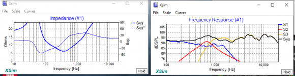
The amount of overlap between drivers seems a little different, along with the extremely narrow pass band for S2.
And is that 50 mH on L2? That's extremely large.
There are CircuitBlocks in XSim that will give you more typical values for standard crossovers.
And is that 50 mH on L2? That's extremely large.
There are CircuitBlocks in XSim that will give you more typical values for standard crossovers.
Last edited:
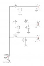
Most of the parts values look impractical; why don't you tell us what the drivers are and what your chosen crossover frequencies are?
(& the baffle width)
(& the baffle width)
Tweeter: https://www.parts-express.com/Dayton-Audio-DC28FS-8-1-1-8-Silk-Dome-Shielded-Tweeter-275-075Most of the parts values look impractical; why don't you tell us what the drivers are and what your chosen crossover frequencies are?
(& the baffle width)
Mid: https://www.parts-express.com/Wavec...id-Woofer-with-Truncated-Frame-8-Ohm-298-1142
Woofer: https://www.daytonaudio.com/product/1563/tcp115-8-4-treated-paper-cone-midbass-woofer-8-ohm
I chose a crossover frequency of 350hz and 2500hz. Not too sure on the baffle width. Thank you.
Thank you very much. Not sure how I should fix this. Will this work?The amount of overlap between drivers seems a little different, along with the extremely narrow pass band for S2.
And is that 50 mH on L2? That's extremely large.
There are circuit blocks in XSim that will give you more typical values for standard crossovers.
Thanks for the help. Im not sure how to fix this.1, 2, and 3 look kinda big - wont there be a lot of power lost in those?
That calculator will also get you in the ballpark.
When XSim is fed the proper files for impedance and frequency response, it uses the actual driver impedance throughout the frequency range to accurately simulate the crossover and speaker response. The Omnicalc one is just using a flat 8 ohm, 4 ohm, etc. value, so that's less accurate in practice. It will give you some standard crossover values to begin with though.
Typical cross points would be something like 500 Hz and 3000 Hz. So the woofer would handle 20 Hz to 500 Hz. The midrange would handle 500 Hz to 3000 Hz. and the tweeter would handle 3000 Hz to 20 kHz. These aren't necessarily the "correct" numbers for you drivers, just ballpark start points.
Normally padding is avoided on the woofer, so R3 would typically not be used. R1 and R2 would then be significantly smaller.
thank you so much! I really appreciate it! Should I add padding to the tweeter and mid? I have a prebuilt crossover built by dayton and the highs sound very high. Should I use a resistor or make an LPad? Also, would it be the worst Idea to just use the schematic omni calc gives to me?That calculator will also get you in the ballpark.
When XSim is fed the proper files for impedance and frequency response, it uses the actual driver impedance throughout the frequency range to accurately simulate the crossover and speaker response. The Omnicalc one is just using a flat 8 ohm, 4 ohm, etc. value, so that's less accurate in practice. It will give you some standard crossover values to begin with though.
Typical cross points would be something like 500 Hz and 3000 Hz. So the woofer would handle 20 Hz to 500 Hz. The midrange would handle 500 Hz to 3000 Hz. and the tweeter would handle 3000 Hz to 20 kHz. These aren't necessarily the "correct" numbers for you drivers, just ballpark start points.
Normally padding is avoided on the woofer, so R3 would typically not be used. R1 and R2 would then be significantly smaller.
If you look at the driver sensitivities, that helps explain why the tweeter sounds too loud.
The tweeter is 89 dB at 2.83 V at 1 meter.
The midrange is 84 dB.
The woofer is about 82 dB.
So if you are OK with the midrange level in comparison to the woofer, the tweeter needs to come down about 5 dB. You can use a resistor before the tweeter crossover as you have in your original diagram (R1). Around 6 ohms is probably about right.
An L-pad between the crossover and tweeter is also a standard way to do this. For 5 dB attenuation, a standard L-pad would be 3.5 ohms for the series resistor and 10 ohms for the one parallel with the driver.
In the end, padding is often adjusted by ear, so your preference drives this on both the midrange and tweeter levels. If you decide the midrange also needs to come down in level, then the tweeter will need to come down farther to balance with the midrange.
If power input is moderate, 10 watt resistors for padding will likely be OK in the midrange and tweeter circuits.
Sorry, forgot the last question.
The Omnicalc circuit will likely be similar to the prebuilt one from Dayton. Both are assuming flat frequency response and flat impedance. That will work, but it won't be optimized for the drivers you are using. With 12 dB slopes and reasonable cross points, you'll likely be OK from a function standpoint. If it sounds good to you, that's good enough. It really comes down to how much work you want to do and what it takes to make you happy.
The Omnicalc circuit will likely be similar to the prebuilt one from Dayton. Both are assuming flat frequency response and flat impedance. That will work, but it won't be optimized for the drivers you are using. With 12 dB slopes and reasonable cross points, you'll likely be OK from a function standpoint. If it sounds good to you, that's good enough. It really comes down to how much work you want to do and what it takes to make you happy.
Thank you. So should I use the Omni calculator and then add these components in?If you look at the driver sensitivities, that helps explain why the tweeter sounds too loud.
The tweeter is 89 dB at 2.83 V at 1 meter.
The midrange is 84 dB.
The woofer is about 82 dB.
So if you are OK with the midrange level in comparison to the woofer, the tweeter needs to come down about 5 dB. You can use a resistor before the tweeter crossover as you have in your original diagram (R1). Around 6 ohms is probably about right.
An L-pad between the crossover and tweeter is also a standard way to do this. For 5 dB attenuation, a standard L-pad would be 3.5 ohms for the series resistor and 10 ohms for the one parallel with the driver.
In the end, padding is often adjusted by ear, so your preference drives this on both the midrange and tweeter levels. If you decide the midrange also needs to come down in level, then the tweeter will need to come down farther to balance with the midrange.
If power input is moderate, 10 watt resistors for padding will likely be OK in the midrange and tweeter circuits.
Since you already have the basics in XSim, you can take the values from Omnicalculator and put those into your XSim model. Then you'll also have the opportunity to make other adjustments and see how the individual driver responses vary from your original design.
I tried doing that and the frequency response curve looked all messed up. If I added screenshots would that help?Since you already have the basics in XSim, you can take the values from Omnicalculator and put those into your XSim model. Then you'll also have the opportunity to make other adjustments and see how the individual driver responses vary from your original design.
Yes. It should also be possible to save your Xsim file and post it if you have the need.

I did notice that. One moment. ThanksYes.
Also, with 12 dB/octave crossovers, the midrange polarity is typically inverted.
What is 12 dB/octave?Yes.
Also, with 12 dB/octave crossovers, the midrange polarity is typically inverted.
Yes.
Also, with 12 dB/octave crossovers, the midrange polarity is typically inverted.
Attachments
- Home
- Loudspeakers
- Multi-Way
- Crossover Design Help