Folks:
At the risk of over-stepping bounds here, I'm planning on attending Burning Amp. If anyone who wants to enter the contest is interested, I'd be happy to be your team member. If you win, I'd also be happy to ship everything to you at your cost. I don't want anything in return.
Regards,
Scott
Hi Scott, I'm going to submit an entry, I've asked if any of the mods are going, didn't get a response yet. I don't think I have much chance of winning, but murphies law and all that 😉
I'm thinking that shipping may not be worth it but if by some fluke I did win, I'd want the prize to go to someone who could use it (I'm sure there would be someone in the bay area who would like a speaker project). Anyway if no Mod's put their hand up, if you would be willing to hold onto it till someone suitable could pick it up, or keep it yourself! (on the remote chance I actually won) that would be great.
I must say Charlie, this has been a real challenge! I would never have even have attempted to pair these two drivers, except perhaps for an MTM.
Tony.
Tony:
I'd be pleased to partner with you. In the event you win, another option is that you post the prize for sale. I could ship everything for you and only ask that you reimburse me those costs.
Good luck!
Regards,
Scott
I'd be pleased to partner with you. In the event you win, another option is that you post the prize for sale. I could ship everything for you and only ask that you reimburse me those costs.
Good luck!
Regards,
Scott
I must say Charlie, this has been a real challenge! I would never have even have attempted to pair these two drivers, except perhaps for an MTM.
I would have loved to make an MTM contest, and award all six drivers to the winner, except only the two woofers were donated by the reseller. Someone could always buy two more woofers and build an MTM. If an active crossover were used you could more or less just adjust the levels and you would be fine because the design axis is the tweeter center.
If an active crossover were used you could more or less just adjust the levels and you would be fine because the design axis is the tweeter center.
Good idea because the one woofer after baffle step seriously limits the sensitivity of this system.
The entry period has now closed and we are no longer accepting entries.
Check back in a few days for info on the winning entry!
Check back in a few days for info on the winning entry!
...and the winner and runner-up in the 2015 Burning Amp Crossover Design Contest are:
We had quite a few good designs and the judges spent quite a bit of time comparing each beyond simply looking at the submitted info. My thanks go out to them for serving on the panel.
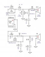
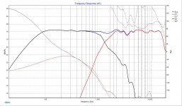
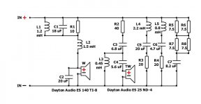
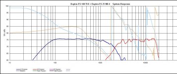
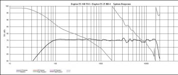
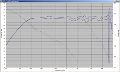
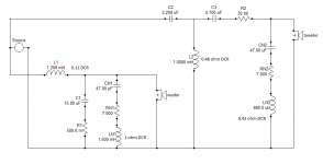
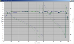
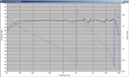
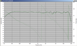
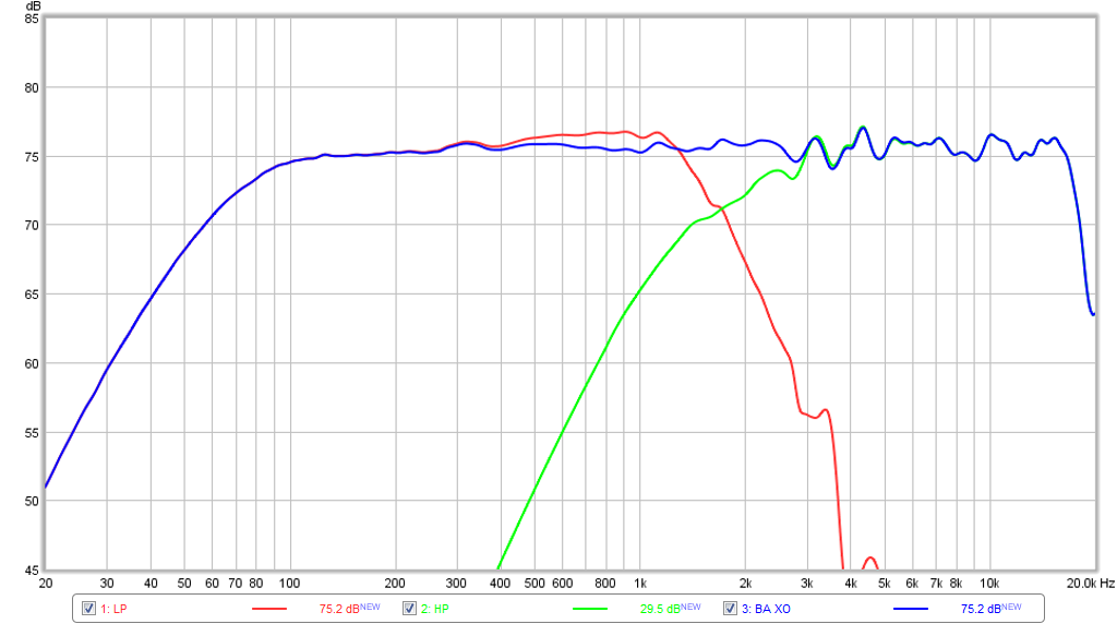
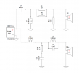
Below you can find the crossover schematics for the winning and placing designs as well as the system responses for each (first two are from winning entry, remaining three are for runner-up. You can also look at the filenames by hovering over the icons before opening them).
.
- WINNER: 4thTry (PE TT user name)
- RUNNER-UP: Lojzek (DIYaudio user name)
We had quite a few good designs and the judges spent quite a bit of time comparing each beyond simply looking at the submitted info. My thanks go out to them for serving on the panel.
Below you can find the crossover schematics for the winning and placing designs as well as the system responses for each (first two are from winning entry, remaining three are for runner-up. You can also look at the filenames by hovering over the icons before opening them).
.
Attachments
Congratulations to 4thtry and Lojsek! I'm going to have to digest those designs, some interesting stuff there! 🙂
Tony.
Tony.
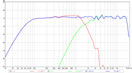
As always I like to compare how others do things to how I have done something. I just modeled 4thTry's crossover (had to do it in speaker workshop as I can't work out how to get that topology in PCD) and compared against my implementation. It's interesting to see the similarities (basic driver characteristics) despite very different implementations.
I was struggling with how much attenuation was required, and tried to squeeze a bit more sensitivity out (going for a 77db target) That cost me in the bass from 200Hz down.
Attached is the comparison 1st showing the sensitivity difference, and then with mine dropped 2db to see how close (other than the bass) they are.. pretty close considering the different topologies and crossover points! edit: mine is the blue curve in both 😉
I'll do lojzeks later (coil dcr would be nice) I've exceeded my lunch hour 🙂
my coil values were:
L1 1.2mH 0.11DCR
LN1 1.5mH 1 ohm DCR
L2 1mH 0.48 DCR
LN2 0.80mH 0.43ohm
Tony.
Attachments

Last edited:
Thanks Tony !
L1 1.2 mH; dcr 0.33; 15 awg
L2 1.5 mH; dcr 0.38; 15 awg
L3 0.45 mH; dcr 0.46; 20 awg
L4 2.2 mH; dcr 0.84; 18 awg
L5 0.8 mH; dcr 0.62; 20 awg
L1 1.2 mH; dcr 0.33; 15 awg
L2 1.5 mH; dcr 0.38; 15 awg
L3 0.45 mH; dcr 0.46; 20 awg
L4 2.2 mH; dcr 0.84; 18 awg
L5 0.8 mH; dcr 0.62; 20 awg
Anybody noticed something about this tweeter?
Dayton Audio ES25Nd-4 1" Ring Dome Neodymium Tweeter 4 Ohm
A ludicrous value, well maybe not for a woofer, but for a tweeter? 😕
A 5" 7L closed box woofer and a ring radiator. Is that hard? I'm not spending time on it. 😀
Dayton Audio ES25Nd-4 1" Ring Dome Neodymium Tweeter 4 Ohm
Voice Coil Inductance (Le)0.95 mH
A ludicrous value, well maybe not for a woofer, but for a tweeter? 😕
A 5" 7L closed box woofer and a ring radiator. Is that hard? I'm not spending time on it. 😀
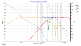
OK here are the comparisons of Lojzeks implementation. Only small differences to 4thTry's
I've often read that dips are less noticable than peaks and it looks like 4thTry has gone with that thought when you look at the the peak/dip in the 3-4Khz range.
I really struggled trying to get rid of the dip in the 1-2Khz range, and gave up in the end thinking it wasn't possible, but Lojzek has succeeded exceptionally well in this regard!
first attachment is comparison between Lojzek and 4thTry's.
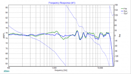
second attachment is comparison between Lojzek and Mine (with mine scaled down 2db).
Third attachment is comparison between all three.
So my assement of my own work after seeing these is:
I underdid the bafflestep compensation a bit. and I overdid my notch a bit, and probably should have concentrated a bit more on the peaks rather than worrying about that making the dips deeper 🙂
I'm interested to see other peoples designs too. Don't be shy 🙂 (Though I'll leave the comparisons at that... though If someone posts I will quite possibly sim it myself for my own curiousity, especially if you have something a little esoteric!
Note that these sims are all comparable, but as SpeakerWorkshop does not have the ability to put in vertical driver offsets (like PCD), I have had to fudge it with slightly more Z offset on the woofer.
Tony.
I've often read that dips are less noticable than peaks and it looks like 4thTry has gone with that thought when you look at the the peak/dip in the 3-4Khz range.
I really struggled trying to get rid of the dip in the 1-2Khz range, and gave up in the end thinking it wasn't possible, but Lojzek has succeeded exceptionally well in this regard!
first attachment is comparison between Lojzek and 4thTry's.
second attachment is comparison between Lojzek and Mine (with mine scaled down 2db).
Third attachment is comparison between all three.
So my assement of my own work after seeing these is:
I underdid the bafflestep compensation a bit. and I overdid my notch a bit, and probably should have concentrated a bit more on the peaks rather than worrying about that making the dips deeper 🙂
I'm interested to see other peoples designs too. Don't be shy 🙂 (Though I'll leave the comparisons at that... though If someone posts I will quite possibly sim it myself for my own curiousity, especially if you have something a little esoteric!
Note that these sims are all comparable, but as SpeakerWorkshop does not have the ability to put in vertical driver offsets (like PCD), I have had to fudge it with slightly more Z offset on the woofer.
Tony.
Attachments
I wonder if a preference was given to passive designs? I had a design that was active and used a Harsch quasi transient perfect crossover at 1670Hz that could play square waves fairly well and had a nice triangle step response. It was 75dB and +/-1dB over range except for the two peaks/dip near 3k which was +/-1.5dB.
I feel like a bit of a party-pooper here, but these cheap knockoffs of Dynaudio's large voicecoil polycones, and Vifa and SB acoustics ring radiators just suck to the highest degree.
These must come from a part of the World that has no respect for patent law at all, which is strange because Dayton Audio portrays itself as being as American as apple pie. 🙄
As for that woofer. I mean really, why are we having to deal with such a horrible peak at 3.5kHz. Well, because it's an unsuitable glass fibre cone.
Sorry, but someone ought to say this. 😡
Attachments
As for that woofer. I mean really, why are we having to deal with such a horrible peak at 3.5kHz. Well, because it's an unsuitable glass fibre cone.
I would not have chosen this combination of drivers either, but thought maybe they were paired together to provide a challenge to make us flex our brains in coming up with a XO. Given the major peak on the woofer and several peaks and dips on the tweeter, it was not as easy a task like taking a flat-as-a-board AC130F1 and RS28A like the drivers in the Continuum.
Here was what Anthony Bisset and I came up with:
Impulse:
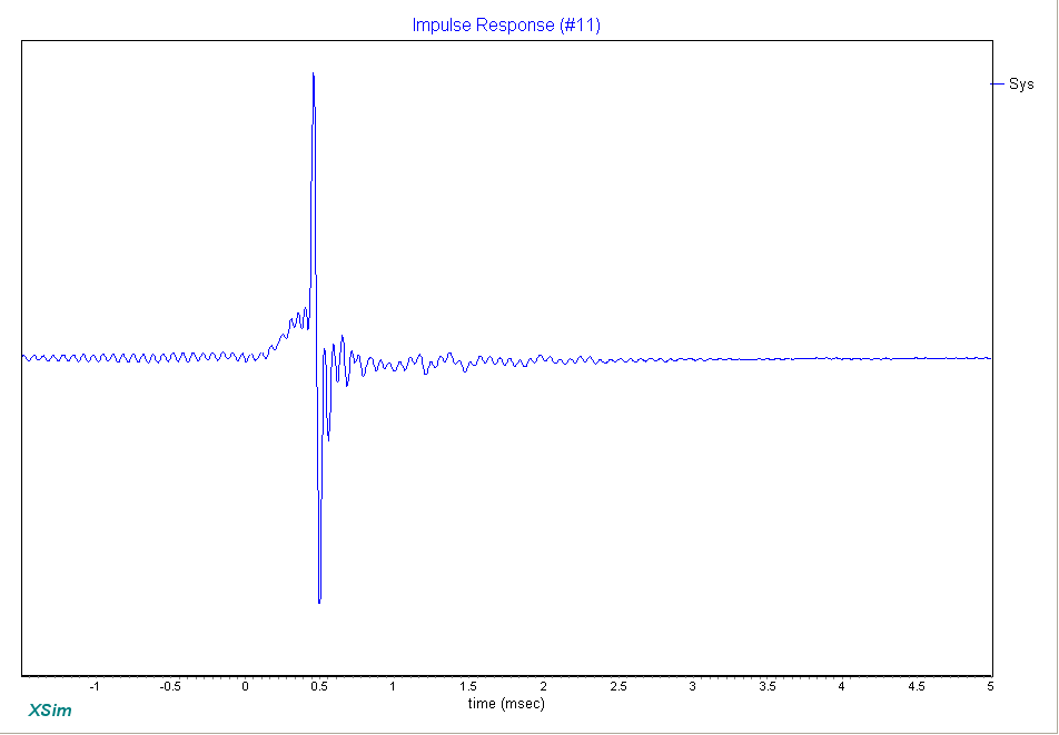
Step:
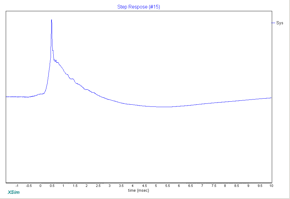
Attachments
Last edited:
I would not have chosen this combination of drivers either, but thought maybe they were paired together to provide a challenge to make us flex our brains in coming up with a XO. Given the major peak on the woofer and several peaks and dips on the tweeter, it was not as easy a task like taking a flat-as-a-board AC130F1 and RS28A like the drivers in the Continuum.
You are all giving me too much credit, as if I carefully "crafted" the competition and intentionally chose these drivers to challenge people. Hardly that. I got some drivers donated, realized they could be used to make a pair of small MT monitors, and hatched a plan to get people doing something. Then I threw together the rules, found three judges to commit their time, and made the measurements (including cutting a baffle for the box myself) all in 1 week before finally announcing the contest.
Hopefully I can do this again with alot more advance planning, a better set of drivers, and so on. This was, let's say, a fun first try at this kind of thing. So please don't take it too seriously or point out all the flaws in the system or drivers.
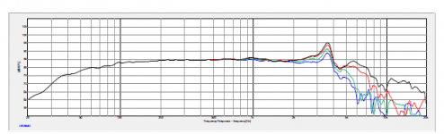
Ok, here's mine. Although Charlie made it clear that complexity wasn't an issue, for the sake of the exercise I tried to keep it as simple as possible, so it's your run of the mill cap - coil - L-pad on the tweeter and coil - resistor+cap - LC notch on the woofer. I used two 25R in parallel in the L-pad to be on the safe side re. power handling, but I guess a single 10W 12.5R would be fine too. My DCRs are: L1 - 0.43, L2 - 0.154, L3 - 0.27.
I've compared it to Lojzek's (last picture, green mine, blue his) and I'm with Tony that he's done a great job flattening it in the 1-2k region, as has 4thTry, and both of them without undue complexity. I've used 4thTry's topology before but, for some reason, it hadn't occured to me to put the trap before the coil and cap as Lojzek did. That goes in my toolbox!
Congratulations to the winners and many many thanks to Charlie, this was fun!
Cheers,
Cabirio
Attachments
Last edited:
A ludicrous value, well maybe not for a woofer, but for a tweeter? 😕
I'm not sure why Dayton Audio went with the 1 kHz value. This
is the capacitive region with the phase angle being negative and
if you calculated it for another tweeter, in the same way Dayton did,
you would be looking at a similar value. The VC inductance at 7000 Hz
is about 0,05 mH.
- Status
- Not open for further replies.
- Home
- Loudspeakers
- Multi-Way
- Crossover Design Contest! Win Prizes! Active or Passive! Entries due by OCT 9th.