Are there any good resources on crossover coil crosswalk and coil placement?
I recently got a speaker kit, my second speaker build, which after looking at the crossover PCB, it appeared to me that there would be significant mutual induction based on things i knew from work in RF. So i tested this. and sure enough the mutual induction was significant, how significant, were talking -28 db of signal induced into 1 inductor under load, now imagine that multiplied by the number of cross mutual inductance possibilities and phase differences... yea.. gets worse fast.
I did search for some searches for resources on this topic and didn't find any that quite answered ones typical questions on coil placement and crosswalk completely, though some good high level guidelines, and some not so good, but in general left a lot of practical questions unanswered i thnik some of this information likely lead to some of what i am seeing in my particular example of a crossover.
I've considered doing my own write-up on this, though to do this in the detail it deserves would be a bit of work. So i am looking to see if this has already been done
here are the resources i've found and some of what i found lacking.
respects.Inductor Coil Crosstalk Basics | Audioholics - seemed accurate for what was there but incomplete, and dint give real measurements and practical formulas enough info to solve ones challenges. Defiantly in the right direction though, needs expanded on.
Crosstalk measurements between inductors -
Techtalk Speaker Building, Audio, Video Discussion Forum - this looked like it might have been a good set of tests, but, seems it was pulled by the author.
Placement of coils in crossover networks - delt with changes in the values of conductors and not with the nutual induction / cornstalk directly. also didn't deal with off angle issues.
Loudspeaker Inductor Crosstalk Measurements — Polk Audio - not sure i like how it was done, used an lcr meter as the signal soruce. under load the input would be loaded and that wasn't taken into consideration, number of -db of crosstalk would have been informative at various distances and angles. in sort .. love to have more information.
in general, i see how information on what happens at off angles, which seems to be a common layout decision. like a right angle but off center, what effect does it have.
so anyway not putting down any of the above, just wishing there was more verified information basically. for the above tests i am sure they used what they had, and in similar fashion id use what i have.
i think some of the assumptions and recommendations i see on forums retarding crossover coil placement are not the full story and i know not everyone has tools to actually test what the interactions are.
on the flip side, i think any tests done should be reproducible by anyone. this gets rid of any "you didn't est this factor" heck you can do it yourself and see and make your own conclusions.
so yea if there is any better test and write-ups id love to know. if there is any value in doing a write up, and some theoretical explanation / demonstration id love to hear that too, as i have an opportunity right now to actually run the tests and demonstrations and document the results before i assemble this speaker 🙂
Last edited:
Troels Gravesen probably did the best work on crossover placement.
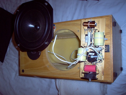
It's coils that interact, both with each other and thick metal ground planes.
Keep them at right angles or distant from each other.
This is a 1mH ferrite. The value is reduced by a nearby metal plate, here an ashtray, and the inductance test tone at 1kHz from my meter feeds back to the tweeter for an audible whistle:
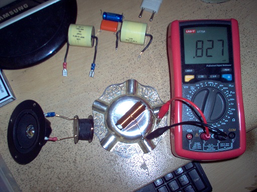
Thin metal doesn't seem to affect things much, and caps and resistors have no interaction at all. But I do point to point wiring and 90 degree placement just in case.
It's coils that interact, both with each other and thick metal ground planes.
Keep them at right angles or distant from each other.
This is a 1mH ferrite. The value is reduced by a nearby metal plate, here an ashtray, and the inductance test tone at 1kHz from my meter feeds back to the tweeter for an audible whistle:
Thin metal doesn't seem to affect things much, and caps and resistors have no interaction at all. But I do point to point wiring and 90 degree placement just in case.
FWIW I did specific tests on inductor crosstalk (voltage) and mutual inductance effects a number of years ago. Assuming you are using air-cored inductors, as long as there is a 2-inch clearance between the perimeters of adjacent coils, voltage crosstalk is at least -50 dB, and inductance changes are 1% or less with the coils laid down flat (no need to stand the coils up and/or rotate them 90 degrees).
Paul
Paul
'Star' wiring the ground (the - negative return of the speaker cable) may also help reduce audio injection into the tweeter's circuit.
Crossover networks 'floating above ground' produced through conductor resistance of the wiring lends it to being more sensitive to external fields than it would be if it is grounded at one point.
Don't just relie on a soldered joint but a twisted connection of the lead wires helps to ensure a positve low resistance joint. Figure 8 cable with a few twists from the crossover to the driver helps too.
C.M
I have to agree with Steve. The amount of interaction between a coil and a plane beneath it is really pretty high. Avoid using any PCB traces beneath a coil.
-28dB is quite far down for the fundamental. Inaudible, in the presence of another driver playing at 0dB. The exception to this is if the driver produces a very high amount of distortion at the crosstalk frequency - i.e. you might not want a tweeter to receive 30Hz at -28dB.
I would give more attention to keeping inductors away from small ferrous objects such as screws as they can easily saturate and cause significant distortion.
I would give more attention to keeping inductors away from small ferrous objects such as screws as they can easily saturate and cause significant distortion.
FWIW I did specific tests on inductor crosstalk (voltage) and mutual inductance effects a number of years ago. Assuming you are using air-cored inductors, as long as there is a 2-inch clearance between the perimeters of adjacent coils, voltage crosstalk is at least -50 dB, and inductance changes are 1% or less with the coils laid down flat (no need to stand the coils up and/or rotate them 90 degrees).
Paul
very interesting, i didn't get the same results, but, its very dependent on a lot of factors so don't take that as my saying it is wrong. Which is kind of where my question lies. its less about how to do it, since i've done some tests myself, but, if it is clearly documented and explained anyplace.
interesting, I've never considered that in a factor for introducing singlals into the tweeter path, i'll have to play with it and see the effects myself. Thanks'Star' wiring the ground
C.M
I have to agree with Steve. The amount of interaction between a coil and a plane beneath it is really pretty high. Avoid using any PCB traces beneath a coil.
hmm, interesting observation... i'll ahve to test that for myself and see ... id be curious how bad a factor that is, just seems the coupling would be rather low in general. but like many things, you never know till you actually set it up and test. Thanks
-28dB is quite far down for the fundamentals. Inaudible, in the presence of another driver playing at 0dB. The exception to this is if the driver produces a very high amount of distortion at the crosstalk frequency - i.e. you might not want a tweeter to receive 30Hz at -28dB.
I would give more attention to keeping inductors away from small ferrous objects such as screws as they can easily saturate and cause significant distortion.
it is funny, 2 of the places that received -28db directly was on the tweeter and the midrange were there is an inductor directly in parallel with the driver. the actual total signal-induced is actually higher because each of them are within the field of 2 other inductors.
and really it is all not as simple as that as not only is there induction of frequency ranges not intended to be covered by a particular driver in your crossover design but out of phase signals both in and outside of the designed band. this causes phase distortions not just within the crossover network but between the drivers as well. from a system wide perspective basicly its a real mess.
-28db would be about 4% distortion (3.9%)... not sure if you have played around with positions of inductors in a live system, but its definitely audible if there interacting significantly. the human ear is quite sensitive to phase changes too....
at what levels is it audible, ... i've not done that kind of critical listening but id like to think I could hear the difference 4% distortion would make. the more critical a listener you are, the more you could notice differences i am sure.
defiantly measurable though, unlike many things that make something sound better.
remember that -28db figure is going to be a lot higher for the system in total as that only took into account one interaction in 1 direction.
in the example, i am looking at of the 4 inductors in this particular crossover network and i can measure significant interactions in 8 directions so just for argument sake, you could be talking about -28 * 8 in total system mutual induction. that be about -19 db or around 11% distortion if it is all effecting the drivers which it all would not of course...... as this doesn't take into account what happens post that induction and other circuitry past that point...nor how strong the field would be given the signal/current passing through the inductor .. so it is just an illustration how bad it could get pretty quickly. so i do not think the overall effect would be quite that high, its only an illustration of how things compound. also if you introduce an out of phase-shifted singal, it doesn't create 100% distortion, so there are all those factors.
its kind of interesting now having played with it a bit. i am curious if you ever did experiments around this and heard/seen the interactions?
Last edited:
When I ran my tests on mutual inductance, I presented my results in the PE Tech Talk forum here:
My take on inductor spacing -
Techtalk Speaker Building, Audio, Video Discussion Forum
Then I posted this to address voltage crosstalk:
My take on inductor spacing -
Techtalk Speaker Building, Audio, Video Discussion Forum
Then I posted this to address voltage crosstalk:
Attachments
When I ran my tests on mutual inductance, I presented my results in the PE Tech Talk forum here:
My take on inductor spacing -
Techtalk Speaker Building, Audio, Video Discussion Forum
Then I posted this to address voltage crosstalk:
Very cool, thanks!!
- Home
- Loudspeakers
- Multi-Way
- Crossover Crosstalk - any good resorces?