yes i see you used MR, simply fantastic!
I did in the treble. I credit them with helping me land my current girlfriend. 🙂
System7 posted about capacitive coupling with coils and then we did some tests using aluminum foil to simulate that bass crossover you see in the pic. Turns out there's a lot of measurable, complicated interaction when you do that, so sometime soon I'm going to disconnect the coils from the lands underneath.
Best,
Erik
Just FYI, the treble is a Mundorf AMT, which sounds and measures impossibly good. The price of the tweeters made the expensive MR caps seem cheap. 😀 😀
Any thought about the russian MKT K73-16 ?
What to think about large capacitance value : more than 200 uF electrochemical bypassed with 0.1uF Styrene or MKP ? Snake oïl or valid in some design ?
What to think about large capacitance value : more than 200 uF electrochemical bypassed with 0.1uF Styrene or MKP ? Snake oïl or valid in some design ?
Eldam,
Bypassing electrolytic capacitors is standard engineering practice but i would do no less than 1%. If the electolytic is 200 uF i would bypass with a 2uf film, but that's just a rule of thumb. If I was building for cost effectiveness, I would measure the caps independently and together with something like DATS across the audio spectrum, and compare it to the voltages the cap expects to see. I can use XSim for instance to see the voltage on each part. If the voltage to an electrolytic cap will roll off after 200 Hz, then bypassing won't do a lick of good. However, as the second pole in a low pass filter, it's more critical to ensure proper functioning. So, not snake oil, but not always needed.
Since caps this large tend to be in the woofer sections, you may need zero bypassing, but 2uF film caps are cheap. One other thing, electrolytics tend to be less accurate and less stable over years than film caps. Often film caps I buy are within 1% of the label. Personally I would probably try to buy inexpensive Axon caps to make up to 200uF unless it was just a really cheap build. They come in 50uF sizes or close to that.
Snake oil may definitely occur when it comes to bypassing and mixing and matching film caps. Only your own ears will help you there. My rule of thumb for tweeter sections however is to not use any single cap larger than 5uF. If I need 10, I'll try to use two 4.7 and a 0.68 of the same kind. With some brands it's almost the same price as buying a single large cap. With others like Clarity though this can be expensive.
Best,
Erik
Last edited:
thanks Erik, good tips...
That's a little what I believed : many brands bypassed (still do?) their mid and tweeter systematicly with 0.1 uF without too much ask themselves if the tonal balance was better. Was it for the hifi magazine ? (good speaker must have a good bypass with famous brand too ?! ). I say that just because I saw too much 0.1 uf everywhere in many reviews. But sure I can hear the difference between two different 0.1 uF : so not a neutral practice, Something happens (for the best or not...with each speaker)
In the case of my main speaker I have MIT styren 0.1 uF // with Mylar and lytic as well, even in the shunt of the bass high pass filter !
Maybe there is a logic, or maybe it was an engineering practice everybody used to do... (for the consumers, the marketing side...above the technical accuracy)
btw hard to know for the enthusiast if swaping lytic for MKP will not make the things worst as already pointed out in a post above if the designer knew what he did ! Try & error is a little expensive with speaker caps... But the Clarity ESA seems attractive for large values...
I don't know where Boston Acoustic is sourcing its OEM caps (yellow lytics) !
Last edited:
Bypassing is also cost effective measure. A 30uf elec. Bipolar is a lot lot cheaper than film equivalents. if i was forced to save money by sticking to cheapest possible caps i would probably try to squeeze in bypass film caps as a matter of habit. Also, older elec. Caps were more inductive than they are now, so if you have been looking at old crossovers im not surprised you see so many bypass caps
I recently made up some 2000uF lytic polarized caps, and placed them in series to make a 1000uF cap using 330uF caps in bundles of 6. I then tried the possibility of voltage biasing them, and at this point, I have not heard a difference between no voltage and biased. I ran them with 12VDC.
This is for a switchable HP filter I call a 'rumble switch'.
Later,
Wolf
This is for a switchable HP filter I call a 'rumble switch'.
Later,
Wolf
Some electrolytics are quite free of character as they are, so.. I've been down this road, and I don't remember much of it so maybe that speaks for itself still, not all caps are created equal.I then tried the possibility of voltage biasing them, and at this point, I have not heard a difference between no voltage and biased.
Here is my two way crossover. Biggest film cap is 51uF. Crossover point is 2.8Khz, the 51uF is part of a notch 🙂
Tony.
Hi.
Do you make your own inductors? I'm interested in learning how to do that.
Hi.
Do you make your own inductors? I'm interested in learning how to do that.
You have to make a jig and have either a turn calculator or an LC meter of some kind. A DATS or WT2 can suffice as an L-measurement tool as well.
As long as you can do these things, then you can sit for a bit and make a few coils. 😀
Here's how I do it.
1- cut 2x 6" circles out of some rigid 1/4" thick substrate. I used acrylic/plexi/lexan stuff, as it allows me to view things through it easier. I used a v-groove bit set to half thickness of the substrate, and then flipped the unit and cut the other side. Sand to remove roughness.
2- cut 4 slots radiating from the center, leaving material at the edge and a 1.25" diameter solid area in the middle.
3- drill a 1/4" hole where the center-pin was for your circle jig.
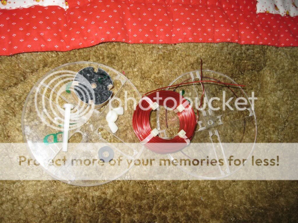
4a- cut a 1.75" diameter, 3/4" thick 'HUB' for the coil former, and notch the circumference in 4 places that line up with your 4 slots. This will allow the zip-ties to slide through after the coil is wound and only wrap the coil itself.
4b- if you want to use pvc pipe for your cores, you won't need a hub, but the hub will allow the center to fit more solidly during winding. You can use 1.5" or 2" PVC or other plastic pipe for your hubs with the dimensions I have listed above. This works extremely well for litz wire due to the flexibility of the litz strands.
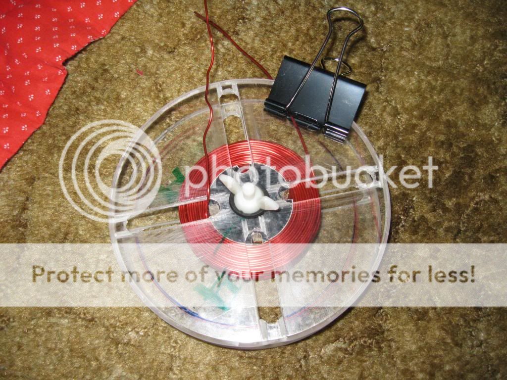
5- Use a non-metal bolt, wingnut, and rubber washer to assemble your jig. I use a nylon 1/4-20 bolt and wingnut so the bolt does not affect the coil's value. The washer is to keep the assembly tight and not spin during winding.
6- scratch off some insulation from the end using sandpaper or a box-cutter knife. this will be point A. Place wire through one slot on one side of the jig from the inside, and bend it over the slot tightly. You may have to hold this end in place as you wind for a few turns to make it stay put. Keep the tension from your spool as tight as possible, or this process will not work at all. It may take some practice. I keep the spool between my feet against the base of the couch while I sit on the couch, and wind from the floored spool (unrolling toward the couch), keeping the tension. If you think you're about where you want to be- scratch some insulation off and measure the inductance. I use a binder clip to hold the incoming wire to the jig and keep tension while I measure. Is it enough? If not, carefully remove the clip and keep going. The next layer will overlay the exposed test point, and it will not be any concern to short against another spot on the wire. Is it too much? You can unwind carefully while keeping tension, and just use the same test point you just did, unless it's quite a bit over where you want to be. You may have to scratch closer to where it needs to be.
7- if you have your value, clamp the incoming lead, and clip its length to your preferred length. (I recommend a lead length of 4-6 inches.) Install one zip tie through the closest slot to your outer lead. Make sure it's TIGHT. Remove the clamp on the lead, pull taut, and bend the lead to make it point at the origin of the coiled-circle. Remeasure. This is to verify you have what you want, as the place of the outer lead's departure from the coil can make a big difference in measured value. You can do this before you clip the wire if you wish, so that you can just keep going by removing the zip tie. If it's indeed still where you want it, install the remaining 3 ties. Make sure they are TIGHT! Clip off zip tie unnecessary length.
8- Disassemble jig and remove the coil. If you went with the hub version so there is no core to the coil, then you may have to gently tap the hub out of the coil with a small hammer or mallet. I usually add 4 more ties for a total of eight unless the wire is litz- then it's as many as necessary to keep it contained in form.
9- Take the 2 leads straight up from the coil, use them as a handle, and dunk the coil in polyurethane. Let drain above the can until minimal, and either hang or set to dry.
Pictures:
Hub and 2 discs from the jig:

Assembled with PVC core:

Wound:
Zipped:

disassembled:
Longer bolt, longer core:
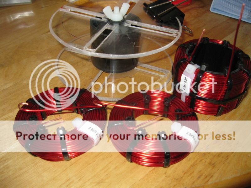
Litz:

Some of what I've wound in networks:
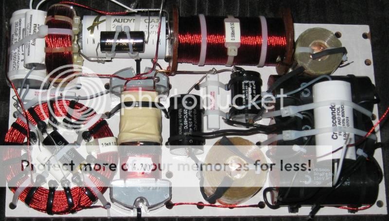
Only the solid-strand airs are mine here:

Hope this helps,
Wolf
Hi.
Do you make your own inductors? I'm interested in learning how to do that.
Yes I do. see here http://www.diyaudio.com/forums/blog...g-your-own-adventure-coil-winding-part-i.html and here http://www.diyaudio.com/forums/blog...-your-own-adventure-coil-winding-part-ii.html 🙂
Tony.
I think I know why your values were less than figured. Aluminum reduces the value of the inductance like a shorted turn in a transformer. Depending on when you measure, this can affect the end result, and is why I use a nylon bolt for the jig.
Later,
Wolf
Hi Wolf, I only measured after removing off the jig (ie air core). I suspect that the problem was probably my winding tension not being high enough, so the windings were not quite as tight as they should have been. It would be interesting to see the accuracy using a smaller gauge wire, the 14ga was a handful for me!
Tony.
Tony.
Instead of using cable ties, could the coil be dipped in varnish or thin epoxy so that is what holds the wire together? - would look neater .... not that neatness is the primary factor.
Yes, both Wolf and I dipped our coils in Varnish (polyurethane), we just didn't take the cable ties off once they had dried 🙂 I'm sure it would be ok to do so though.
Tony.
Tony.
You have to make a jig and have either a turn calculator or an LC meter of some kind. A DATS or WT2 can suffice as an L-measurement tool as well.
As long as you can do these things, then you can sit for a bit and make a few coils. 😀
Here's how I do it.
1- cut 2x 6" circles out of some rigid 1/4" thick substrate. I used acrylic/plexi/lexan stuff, as it allows me to view things through it easier. I used a v-groove bit set to half thickness of the substrate, and then flipped the unit and cut the other side. Sand to remove roughness.
2- cut 4 slots radiating from the center, leaving material at the edge and a 1.25" diameter solid area in the middle.
3- drill a 1/4" hole where the center-pin was for your circle jig.
4a- cut a 1.75" diameter, 3/4" thick 'HUB' for the coil former, and notch the circumference in 4 places that line up with your 4 slots. This will allow the zip-ties to slide through after the coil is wound and only wrap the coil itself.
4b- if you want to use pvc pipe for your cores, you won't need a hub, but the hub will allow the center to fit more solidly during winding. You can use 1.5" or 2" PVC or other plastic pipe for your hubs with the dimensions I have listed above. This works extremely well for litz wire due to the flexibility of the litz strands.
5- Use a non-metal bolt, wingnut, and rubber washer to assemble your jig. I use a nylon 1/4-20 bolt and wingnut so the bolt does not affect the coil's value. The washer is to keep the assembly tight and not spin during winding.
6- scratch off some insulation from the end using sandpaper or a box-cutter knife. this will be point A. Place wire through one slot on one side of the jig from the inside, and bend it over the slot tightly. You may have to hold this end in place as you wind for a few turns to make it stay put. Keep the tension from your spool as tight as possible, or this process will not work at all. It may take some practice. I keep the spool between my feet against the base of the couch while I sit on the couch, and wind from the floored spool (unrolling toward the couch), keeping the tension. If you think you're about where you want to be- scratch some insulation off and measure the inductance. I use a binder clip to hold the incoming wire to the jig and keep tension while I measure. Is it enough? If not, carefully remove the clip and keep going. The next layer will overlay the exposed test point, and it will not be any concern to short against another spot on the wire. Is it too much? You can unwind carefully while keeping tension, and just use the same test point you just did, unless it's quite a bit over where you want to be. You may have to scratch closer to where it needs to be.
7- if you have your value, clamp the incoming lead, and clip its length to your preferred length. (I recommend a lead length of 4-6 inches.) Install one zip tie through the closest slot to your outer lead. Make sure it's TIGHT. Remove the clamp on the lead, pull taut, and bend the lead to make it point at the origin of the coiled-circle. Remeasure. This is to verify you have what you want, as the place of the outer lead's departure from the coil can make a big difference in measured value. You can do this before you clip the wire if you wish, so that you can just keep going by removing the zip tie. If it's indeed still where you want it, install the remaining 3 ties. Make sure they are TIGHT! Clip off zip tie unnecessary length.
8- Disassemble jig and remove the coil. If you went with the hub version so there is no core to the coil, then you may have to gently tap the hub out of the coil with a small hammer or mallet. I usually add 4 more ties for a total of eight unless the wire is litz- then it's as many as necessary to keep it contained in form.
9- Take the 2 leads straight up from the coil, use them as a handle, and dunk the coil in polyurethane. Let drain above the can until minimal, and either hang or set to dry.
Hope this helps,
Wolf
This is great! So is Wintermute's blog. Thank you both!!
I think I can handle building the rig without problem. My follow-up questions are very basic, though: 😱
- What is a DATS or WT2? If it's a Dayton Audio Test System, I don't have it and difficult to source here. WT2 is Larson's Audio Woofer Tester? Similarly, dificult to source here.
- I do have a tester, but I suspect it is not helpful for this.
- I use REW. Can I measure inductance like if measuring T/S parameters on a driver?
- Is there a simple way around it or should I look into sourcing DATS?
- Material used for coils: pros and cons of using stranded cable vs solid core wire? I was thinking heavy gauge wire like the one used for wiring high power (industrial) transformers and motors.
1. Yes dats and wt2 are what you think they are.
1.2. REW should be fine, pretty sure if you measure and inductor or capacitor (in impedance mode) it will give a value in the bottom left corner of the graph.
SpeakerWorkshop will also work (it has a measure passive component function) with a standard impedance jig.
1.3. yes use REW or Speaker workshop (and probably ARTA as well) 🙂
2. I've only used enammeled copper wire, which was motor winding wire or otherwise known as magnet wire. Not sure about benefits of stranded wire.
Tony.
stolen from elsewhere:
3. wire: In almost all cases this will be single strand 'enamel' insulated, also known as magnet wire. The coating is usually of poly vinyl acetal, polyester or polyurethane.
There are some possible exceptions to this choice:
Coils carrying currents above about 3A. If you are using a small diameter core (RM series) it can be difficult to manipulate thick enamel wires. A better idea is to divide the winding up into two or more thinner wires which are wound on simultaneously and joined at the ends. An additional advantage of this approach is that losses due to skin effect are reduced.
I would expect that using multi strand cable, the insulation would take too much space, hence using enamelled wire as above.
- Status
- Not open for further replies.
- Home
- Loudspeakers
- Multi-Way
- Crossover capacitors