Crossovers for cone/dome drivers on flat(ish) baffles are pretty well understood.
Typically the physical layout issue is that the tweeter is a little too far forward on a flat baffle.
The tweeter can be physically moved back or a little time delay added to it in the crossover, especially convenient with a DSP crossover.
All well documented.
But almost the opposite issue occurs when horn mid/tweeters (assumed 2 way for simplicity) are used with cone woofers - the depth of the horn means the mid is delayed.
It is possible to push the horn driver forward to the woofer plane but this can be problematic - physically awkward with a substantial horn and a potential source of diffraction problems for the woofer.
It is possible to delay the woofer but this seems to miss an opportunity.
The delay of the mid would seem to allow a closer approach to a linear phase crossover but without any DSP step.
I have seen little analysis of this, there was a thread a while back but the OP seems to have lost interest.
"Quasi-optimal" crossover for high-efficiency loudspeaker system.
I read the Vanderkooy & Lipshitz articles referenced in the 1st post that supposedly prove the idea is unworkable.
A closer study shows that certain assumptions in their analysis are too restrictive, a practical solution may be possible after all.
It will require asymmetric crossovers for the HP and LP, and probably non standard shapes.
I have found the maths a little difficult, presumably why V & L only looked at the simple symmetric case.
Anyone have any references or ideas on this?
I will start with an example.
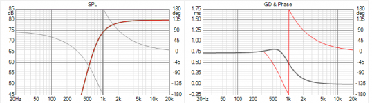
Since we have a time delay an obvious candidate for the Low Pass would be a Bessel filter.
First is a Bessel LP, it has maximally flat Delay.
Second is a HP "Bessel" created by the usual method, the frequency response is mirrored.
But a Bessel is not about frequency response so this does not create a HP with maximally flat delay, as is obvious in the plot.
A closer match would be a HP filter with maximally flat delay.
Anyone know what this is called or have a reference so I don't have to create it from scratch?
David
Typically the physical layout issue is that the tweeter is a little too far forward on a flat baffle.
The tweeter can be physically moved back or a little time delay added to it in the crossover, especially convenient with a DSP crossover.
All well documented.
But almost the opposite issue occurs when horn mid/tweeters (assumed 2 way for simplicity) are used with cone woofers - the depth of the horn means the mid is delayed.
It is possible to push the horn driver forward to the woofer plane but this can be problematic - physically awkward with a substantial horn and a potential source of diffraction problems for the woofer.
It is possible to delay the woofer but this seems to miss an opportunity.
The delay of the mid would seem to allow a closer approach to a linear phase crossover but without any DSP step.
I have seen little analysis of this, there was a thread a while back but the OP seems to have lost interest.
"Quasi-optimal" crossover for high-efficiency loudspeaker system.
I read the Vanderkooy & Lipshitz articles referenced in the 1st post that supposedly prove the idea is unworkable.
A closer study shows that certain assumptions in their analysis are too restrictive, a practical solution may be possible after all.
It will require asymmetric crossovers for the HP and LP, and probably non standard shapes.
I have found the maths a little difficult, presumably why V & L only looked at the simple symmetric case.
Anyone have any references or ideas on this?
I will start with an example.
Since we have a time delay an obvious candidate for the Low Pass would be a Bessel filter.
First is a Bessel LP, it has maximally flat Delay.
Second is a HP "Bessel" created by the usual method, the frequency response is mirrored.
But a Bessel is not about frequency response so this does not create a HP with maximally flat delay, as is obvious in the plot.
A closer match would be a HP filter with maximally flat delay.
Anyone know what this is called or have a reference so I don't have to create it from scratch?
David
Attachments
Last edited:
I've had no problem in the past hitting one side harder than the other, and getting phases and response just where I want them.It will require asymmetric crossovers
I've had no problem in the past...phases and response just where I want them.
Can you show examples, details please?
Best wishes
David
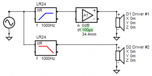
I went digging for plots, then I thought I'd just do something fresh. This is based on flat drivers, crossed at 1kHz. One has a second order filter.
The other is delayed by -250uS (I did this rather than the other at +250uS, so the plots would be easier to read). This delay amounts to 90 degrees, or two extra orders at 1kHz. It has a 4th order filter. It is also inverted as per usual.
The other is delayed by -250uS (I did this rather than the other at +250uS, so the plots would be easier to read). This delay amounts to 90 degrees, or two extra orders at 1kHz. It has a 4th order filter. It is also inverted as per usual.
Attachments
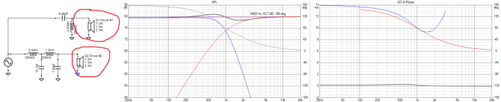
Then I found some old work. I have a mess of these files so I just picked something. Here I have 1st and 3rd order coming together, phase agreeing through the cross, no particular response trend, IIRC I could usually find a way to get it flat. Picture of the design for distance (that's a 15" woofer). Delay appears fairly consistent.
Attachments
Last edited:
I have seen little analysis of this, there was a thread a while back but the OP seems to have lost interest.
"Quasi-optimal" crossover for high-efficiency loudspeaker system.
Hi!
I was the originator of that thread.
The reason I later "lost interest" was the realisation that none of those "quasi-optimal" crossovers had a chance of being correctly implementable in real life, when also duly taking into account the fact that all real exponential or hypex horns already exhibit a "natural" 4th-to-6th order high-pass behaviour at Fc. Therefore, all those nice asymmetrical crossovers that call for a 2nd order high-pass on the tweeter leg are a physical impossibility.
Additionally, what I have come to realise is that what really matters most of all is not minimizing phase rotation of the summed response per se, but rather achieving the best possible phase matching between the two filtered drivers, in a wide frequency range around the acoustical crossover frequency, and up/down to where each driver's response is -12dB.
All of this has led me to re-evaluate the goodness of Pioneer's original passive crossover designs for their Exclusive studio monitors of the '80s and '90s, namely:
- a 6th order electrical LP on the woofer (essentially Linkwitz-Riley)
- a 2nd order electrical HP on the tweeter/horn (quasi-Butterworth)
with BOTH branches wired with the same (+/+) polarity, and the front-to-back offset adjusted so as to achieve the desired optimal inter-driver phase tracking at and around the crossover freq.
This combination seems to work very well indeed for the typical: 15" woofer + ~300Fc Hypex horn, ~600-700Hz crossover, and ~20-25cm offset.
But, the final, real acoustic high-pass transfer function of the tweeter is a combination of the intrinsic acoustic high-pass of the unfiltered tweeter and 2nd order electrical high-pass, and it looks nothing like a textbook high-pass filter (and is certainly NOT 2nd order!).
Cheers,
Marco
The reason I later "lost interest" was the realisation that none of those "quasi-optimal" crossovers [were] implementable in real life...
Hi Marco.
Yes I think this is a critical point and well observed.
But it didn't reduce my interest, just made me curious about what can be implemented in real life.
...(and is certainly NOT 2nd order!).
Yes, the final product will have to factor in both the acoustic and electrical slopes.
If we solve the idealised case, we can consider it as a target and then adjust the electrical response to allow for the acoustic curve.
We don't have to consider the ideal case as some impossibility that needs "mass-less speakers of infinite bandwidth".
Best wishes
David
This is based on flat drivers
As explained in my response to Marco, I think this is the way to study the problem.
Once we understand the idealised case we can include real world effects.
The other is delayed by -250uS...
I see no delay for physical offset in your post, have we failed to understand each other?
Here is an example, it is a Link/Riley with some delay on the tweeter that corresponds to a physical offset.
Best wishes
David
Attachments
Last edited:
The delay was introduced in the form of Z axis offset on the previous tab. Care to elaborate on how the simulation or my real world example could be improved to meet your needs?have we failed to understand each other?
I don't see any Z axis offset in the picture you uploaded, see attached.The delay was introduced in the form of Z axis offset on the previous tab.
But I am not very familiar with VituixCAD perhaps it has been done in some way that I have not come across.
My first impression is that it is desirable that a method to introduce a delay should make that delay visible on the circuit, I would prefer not to have to deduce what has been done on a previous tab.*
Perhaps it will become clearer to me after I am more familiar with VituixCAD, certainly an impressive piece of work.
The real world example is a bit outside my current scope, I'd like to work out the simplified case first, so no comments on that yet but thank you for the offer.Care to elaborate on how the simulation or my real world example could be improved to meet your needs?
Best wishes
David
*OK, I think I can deduce what you have done, I still prefer methods that are clear and obvious.
Attachments
Last edited:
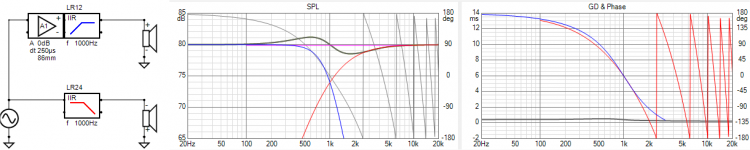
Ok, this is identical. Don't be put off by the phase wrapping, I simply delayed the tweeter instead of advancing the woofer.
This is the most standard beginning as I see it. Both LR. One driver is inverted (I'll try to use a method in the future that makes that fact obvious).
The delay, when looked at over a small band, appears like a filter with regards to phase change, but obviously without the response change.
Where would you like to go from here?
Attachments
This is the most standard...
Yes, I think this an excellent example to start the study.
Like Marco, I don't think it's very realistic but it's more or less canonical.
I have started to achieve some results in simulation that show phase linearization is indeed possible without DSP, which was my point.
I don't yet understand the theory fully but have some ideas so my trial and error at least has some direction.
Best wishes
David
Dave,
it depends on your definition of phase linearization. Normally, phase linearization means that there is no phase shift over the operating range. This is not possible without a DSP that is FIR enabled. Analog filters are always minimum phase. This means that for every rise or dip in the FR, there is an associated phase shift depending of the slope of the rise or dip. Linear phase filtering requires memory which analog filters can't have.
So all analog filters are by necessity minimum phase and they cannot be linear phase.
The trick is to get the phase of two drivers identical at the xover point, including the delay caused by physical misalignment. You can do this, if so required, by applying assymetrical filter slopes to compensate for physical misallignment of the acoustic centre of two drivers. Another possibility could be to use an all pass filter. Or to use odd order filters with reversed polarity between the drivers. It is all dependant on what you want to achieve.
The point being: you cannot linearize phase, but there are good options to get drivers in correct phase at the xover point by using the shifts created by different order slopes of all pass filters. But minimum phase is the best you can do. Which is not problem at all since the sensitivity of the ear for phase shift is still very much being questioned.
For example:
...it depends on your definition of phase linearization.
By phase linearization I mean to make the phase a closer approximation to linear phase.
I don't yet know how closely I can come to perfectly linear phase.
This is not possible without a DSP that is FIR enabled.
Actually it is possible, my main interest in this thread was to explore precisely this question.
Linear phase...requires memory
The time delay of the mid permits essentially the same sort of 'memory' as a DSP.
But minimum phase is the best you can do.
Strictly, yes because the time delay is excess phase, even DSP is subject to this constraint.
But if we don't care about a small additional time delay then we can linearize.
Even without DSP it is possible if we use physical delay.
I must admit I wasn't sure it was practical even if it seemed plausible.
Fun to see the simulations, now to see if I can come up with an analytical solution - the maths is awkward.
Best wishes
David
You need a memory function...
Some of the early computers had a memory function that worked almost exactly this way, kept bits in an acoustic delay line.
Here we still use the acoustic delay line, just don't use bits.
The similarity hadn't come to mind until you reminded me, thanks for the memory.
Best wishes
David
...hopefully...
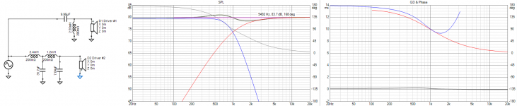
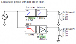
I plan to study it more before I write much, but here's the preview of a first trial.
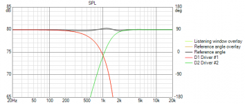
1. The amplitude response is flat to within a few 0.1 dB.
This is almost certainly because I don't have the filter quite perfect yet, in any case it's far below audibility and production tolerances.
Note the scale is maximum expansion to reveal detail, it would look even better on the scale used earlier in the thread.
2. The phase match at crossover is perfect and stays close over the transition band so polar response is optimal.
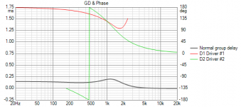
3. The low pass is 8th order yet the delay is small and barely peaked.
A substantial amount of delay has been cancelled.
Note this scale is also maximum expansion and here too would look better on the scale used earlier in the thread.
4. The hi pass is 3rd order, probably the practical minimum when both acoustic and electrical roll-off combine.
5. The offset is more than half a period, which makes a deeper mid horn acceptable.
The time baseline is the mid, the woofer is moved forward in space and effectively in time, this is the "time travel"!
And the maths is awkward.
Best wishes
David
Attachments
Last edited:
David,
This is not a linear phase filter, it is still minimum phase. It is a time aligned minimum phase filter. Better to keep the meaning of words intact.
It is therefore not 'linearizing phase' but 'aligning phase' what you are doing here. That can be done with a delay of any kind, physical or electronic. For linearization, memory is required.
The crossover is not minimum phase, it has excess phase and is essentially an all-pass filter....it is still minimum phase.
The point is that it has half the excess phase of a similar filter without offset.
So the phase has been made more linear, it has been "linearized" - but not completely.
Call it partial linearization if you want to quibble about words.
In fact I doubt this will make an audible difference, even the uncorrected delay is probably below detectable levels on real music.
My primary interest was to allow for the depth of the horn - without the extra step of a DSP - and this has been achieved.
But the linearization is a neat trick and a nice puzzle to see if the mathematics works to allow completely linear phase.
Best wishes
David
- Home
- Loudspeakers
- Multi-Way
- Crossover and time delay/offset, for horns particularly.