Thus the problem must be between the point that signal is lost and the input to the PWM chip. But I want to alert you that if there is along the audio chain an inverting opamp with the NI input grounded, that the signal at the inverting input of the opamp itself vanishes. This effect is natural and don't mean signal is lost, it is converted into a current at that point. Oscilloscopes can't show currents, their input is designed to reproduce voltages as visible light.
You need to investigate why the signal is lost: a shorted semiconductor, a opamp blown or without power, any kind of muting or protection circuit missfunctioning, a broken trimpot, etc.
You need to investigate why the signal is lost: a shorted semiconductor, a opamp blown or without power, any kind of muting or protection circuit missfunctioning, a broken trimpot, etc.

Is this normal, I wouldn’t think it would be since they are overlapping but I don’t have much experience with ClassD so don’t know if this is okay or if am missing something. Probes are on the Drains of each side of the amplifier. I have been looking at schematics and diagrams on how ClassD function so am getting a much better understanding.


The two sides of the amp are driven by two different driver boards which are not, as far as I know, synchronized. If that's true, the pulses won't be perfectly aligned.
Would that be an issue after the issue with the “no” output is resolved? Perhaps with all the filtering going on, it won’t matter but then again am new to this classD.
After hooking up some subwoofers I get very LOW output. With gain set to lowest voltage (fully clockwise) and input 60hz source as high as possible and all am getting out of it is 1.2vAC
After hooking up some subwoofers I get very LOW output. With gain set to lowest voltage (fully clockwise) and input 60hz source as high as possible and all am getting out of it is 1.2vAC
What's the AC voltage at the rear of the RCA jacks?
Is the crossover at the highest frequency?
Is the subsonic set to the lowest frequency?
Is the bass boost set to the highest level?
Is the crossover at the highest frequency?
Is the subsonic set to the lowest frequency?
Is the bass boost set to the highest level?
What's the AC voltage at the rear of the RCA jacks? 500mv (iPhone source, used this with other amps no issues)
Is the crossover at the highest frequency? highest possible 250hz hp
Is the subsonic set to the lowest frequency? Lowest possible 20hz
Is the bass boost set to the highest level? None on this amp but gain is set fully clockwise.
Is the crossover at the highest frequency? highest possible 250hz hp
Is the subsonic set to the lowest frequency? Lowest possible 20hz
Is the bass boost set to the highest level? None on this amp but gain is set fully clockwise.
No difference. Did notice however that the filters work (subsonic works filters fhz below set fhz, the lowpass filter filters anything above set fhz). So seems signal is going through the preamp section and filter section. There‘s 470ohm between input RCA ground and secondary ground and then there is the usual 10Kohm between primary and secondary ground present.
Last edited:
The most common resistor between the primary and secondary ground is 1k. 10k may be normal for this amp.
Which op-amp output pin shows the effects from all front panel controls?
With the gain at the maximum (with 500mv in), what's output level from the op-amp above?
What's the difference in the output level with the gain at either extreme of travel?
Which op-amp output pin shows the effects from all front panel controls?
With the gain at the maximum (with 500mv in), what's output level from the op-amp above?
What's the difference in the output level with the gain at either extreme of travel?
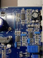
Okay looks like we are getting somewhere, I tracked the signal from the input all the way to the subsonic filter and low pass filter op amps. Then what appears to be a dual op amp that has fresh solder and a mylar capacitor that is easy to point out is not normal (all others are 100v this one is 63v). So appears to have been service at one point and this 072 goes to one side of a 074 inputs and it’s output goes to a resistor and capacitor in series before going to the driver boards as “IN”. By then the signal is 100mv and fuzzy compared to other filters.
For the op-amps in the audio signal path, is there one where you lose signal at its output compared to the output of the previous op-amp in the chain?
The 8-pin op-amp is a buffer. The signal in from the pot (crossover pot?) should be the same as the output of the op-amp.
Are any pins in the telco jack shorted together?
Are any pins in the telco jack shorted together?
Are any pins in the telco jack shorted together? No.
All measurements are in mv. Input signal is 500mv 60hz sine wave.
U11 (First op amp after RCA’s)
1) 460
2) 245
3) 240
5) 240
6) 245
7) 465
8) 51. (This don’t look right to me along with 9 and 10)
9) 51
10) 50
12) 440
13) 440
14) 441
U16 (line out filter?)
1) 346
2) 63
3) 68
5) 50
6) 50
7) 300
8) 460
9) 460
10) 460
12) 40
13) 40
14) 234
U17 (line out filter?)
1) 374
2) 87
3) 87
5) 48
6) 47
7) 290
8) 465
9) 465
10) 465
12) 50
13) 50
14) 255
U14 (subsonic filter?)
1) 200
2) 200
3) 200
5)185
6) 190
7) 200
8) 100 (goes to 2K resistor then 100uf 16v capacitor before going to driver “IN” pin of one card)
9) 50
10) 50
12) 50
13) 48
14) 85 (Goes to a 2k resistor then a 100uf 16v capacitor before going to driver “IN” pin of other card)
Perhaps this amp works phase shifting both outputs in place of modulating the PWM signal. I read an old article from TI about a SMPS with 98%efficiency at 200KHz that maintain 50% duty cycle at both outputs (In such a case driving a transformer) but shifting tbe phase of both outputs with the error signal. Let me see if I can find it.
Edith: Found: slua287
Edith: Found: slua287
Last edited:
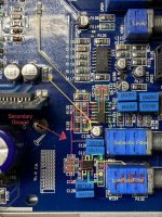
This may not be relevant, but in post #32, is that a solder bridge/ball between pins 8 and 9 of U17?
U17 and U16 have are identical, pin 8 and 9 and tied. Seems like if I put 500mv signal I get out about 750mv-1vAC on the output. I’ll check the R115 and report back today.
It seems to me to be a via under the IC pins.This may not be relevant, but in post #32, is that a solder bridge/ball between pins 8 and 9 of U17?
- Home
- General Interest
- Car Audio
- Crossfire VR4000D no output, 5a 13.6v idle, +/-179vdc rails….