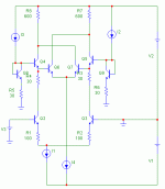
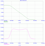
I've read several threads about Professor Hawksford, and I know that he has the cross-quad and cascomp circuits for input stages in a couple of his papers.
Could someone tell me exactly what the advantages are of these circuits (that is, why someone would want to use them)?
Thank you!
Could someone tell me exactly what the advantages are of these circuits (that is, why someone would want to use them)?
Thank you!
http://db.audioasylum.com/cgi/m.mpl?forum=prophead&n=3169
http://www.analog.com/UploadedFiles/Data_Sheets/524850917MAT04_d.pdf
(fig 6)
Hawksford also explored some related diff pair input linearization techniques
J4 DISTORTION CORRECTION CIRCUITS FOR AUDIO AMPLIFIERS, M.O.J. Hawksford, JAES, vol.29, no.7, 8, July/August 1981
At http://www.essex.ac.uk/ese/research/audio_lab/malcolms_publications.html
Somewhere you might also find Gilbert’s “multi-tanh” proposal
Its not clear that these techniques are necessary in audio amplifier design - high loop gain, emitter degen and bootstrapped cascode appear to be enough for super low distortion in audio amp inputs
jcx said:
Somewhere you might also find Gilbert’s “multi-tanh” proposal
http://iroi.seu.edu.cn/jssc9899/33ssc98/33ssc01/pdf/33ssc01-gilbert.pdf
Steven
Quinn's US pat 4897611
it is either 4,146,844 or 4,692,712
4897611 is very high gain positive fb cmos amp
thanx dimitri
4146844 fig 4 looks like what I was thinking of, don't know were my ref came from
I believe the cascomp was actually used in tektronix front end amplifiers - unusual for a patented circuit
The main utility of these enhancements would be in situations where you cannot have high global loop gain
in audio amplifiers it is quite possible to keep the differential input V << 1mV with high loop gain - then the ordinary diff pair is linear enough to not be the limmiting factor
rtarbell said:...Could someone tell me exactly what the advantages (of cross-quad and cascomp circuits for input stages)....
Virtually no value to the designer of discrete amps...
Dimitri, 1968 instead of 1998.
IEEE J. SSC, 1968, pp.353-365
rtarbell,
Also the book "Analog Circuit Design", edited by Jim Williams and published by EDN, has two chapters by John Addis and Barrie Gilbert that might help answer your question.
Tom
see also: B.Gilbert, A new wide band amplifier technique, IEEE J. SSC, 1998, pp.353-365
IEEE J. SSC, 1968, pp.353-365
rtarbell,
Also the book "Analog Circuit Design", edited by Jim Williams and published by EDN, has two chapters by John Addis and Barrie Gilbert that might help answer your question.
Tom
Thanks for all of your inputs! Let me ask, supose I were to make the cascomp in my input stage. I would make the regular differential pair with about 5mA of tail current and an active load to the VAS stage. For the inner differential pair (the cascomp circuit itself), is there any rule of thumb as to what its tail current should be?
Hi Tom2! I have not got it. Can you summarize those chapters? I want to know reason.Also the book "Analog Circuit Design", edited by Jim Williams and published by EDN, has two chapters by John Addis and Barrie Gilbert that might help answer your question
Does Distortion decrease by local feedback or global feedback?
Does this techique have any improvement in a whole amp ? or Is it good when do analysing the only input stage ?
Thanks !
Multi Tanh
Hi
What is the main difference between multi tanh stage and so-called 'schmook pair' ?? the basic idea seems similar to me... has Gilbert re-invented what Schmook had before 😕
Hi
What is the main difference between multi tanh stage and so-called 'schmook pair' ?? the basic idea seems similar to me... has Gilbert re-invented what Schmook had before 😕
Schmook
They seem to be the same, at least for the case 1:n and n:1 cross-connected.
See patent 5933054: http://www.freepatentsonline.com/5933054.pdf
From this patent:
" An example of the conventional bipolar OTAs was disclosed by Schmook in the IEEE Journal of Solid-State Circuits, Vol. SC-10, No. 6, PP. 407-411, December 1975, in which two unbalanced differential pairs of bipolar transistors are employed. Two transistors of each pair has different emitter areas or sizes. Output ends or collectors of the two transistors of each pair are cross-coupled.
The transconductance linearization technique proposed by Schmook is known as the "Multi-tanh" technique, and has been practically used.
An application of this Multi-tanh technique was disclosed y Tanimoto et al., in IEEE Journal of Solid-State Circuits, Vol. 26, No. 7, PP. 937-945, July 1991."
This patent mentions an alternative approach to linearization.
So Schmook's pair is multi tanh.
That's funny, I used to think it's Gilbert's invention.
However Gilbert's article is great in terms of analysis and popularisation.
That's funny, I used to think it's Gilbert's invention.
However Gilbert's article is great in terms of analysis and popularisation.
- Status
- Not open for further replies.
- Home
- Amplifiers
- Solid State
- cross-quad and cascomp circuits


