
Just read the first page of the thread. So excuse me if already inputed.
https://www.diyaudio.com/community/...-design-your-own-speaker-from-scratch.332688/
https://www.diyaudio.com/community/...-crossovers-without-measurement.189847/latest
The latest Dickason loudspeaker coockbook has an enhanced active speaker section and is worthing a read. You will know more about the drivers themselves too to read datasheets.
Beginn by choosing the active dsp setup as the amp : I believe this is the beginning of an active setup and say to people what you start from : mminidsp, hypex, something else pc + soundcard ?
The best imo both for the pocket, time involved, monney, is to pay a little for a well executed passive or active design : not expensive for the work involved and errors (almost) free : Troels Gravsen, heissmann acoustics have active designs for illustration among over ; certainly many usa based exists as well with active and dsp setups.
Another way when knowing few and wanting going for active is to look at passive designs on the drivers vendors sites and elsewhere, names above, or close to you to try to listen it in the country neighborhood : you have fro the start the drivers and the volume cabinets and just have to focus on the active filter and room eq.
illustration of passive diy designs passive you can do active : diysoundgroup, paul Carmody, https://www.speakerdesignworks.com/finalist-monitor.
Basicly in a project you migth targett the time and the monney involved in relation to the budget and the quality ratio you want. It is for the best sound ? The learning purpose and so on . There are trade-offs everywhere and you can not talking about drivers at first without any ideas before about your whishlist. Drivers choices does not comme first in that process. It can when you have minimal experience cause your brain does the shorts very quickly (the so called Experience).
How do i do step 4:
4: Simulate the baffle.
Also, how do i add another driver?
And what do i do next with this diffraction?
4: Simulate the baffle.
Also, how do i add another driver?
And what do i do next with this diffraction?
Attachments

Last edited:
First you will need to design a baffle shape and an enclosure volume for each driver (besides the tweeter, if it isn‘t open back). This can be done in Tools -> Enclosure in the menu. You will need to ensure the correct T/S parameters for each driver are accounted for. Then you will have to merge the enclosure responses with the frequency responses. Then you need to simulate a baffle, like how I explained here.
https://www.audiosciencereview.com/...th-coax-and-woofers.49055/page-2#post-1762431
Is there a guide on how to use the Enclosure tool? BC i dont get it. i find the drivers and then what?
Dont need enclosure.
Just diffraction tool.
Factory impedance curve more accurate.
for crossover design.
If reflex the sim would show the "double hump"
Otherwise worthless info and not accurate for crossover.
You have to cross calculate more advanced T/S parameters
to get a realistic impedance curve. So enclosure
waste of time. Use factory data/trace for ZMA
Establish tweeter position.
Make that listening position.
Place microphone at listening position.
Simulate all drivers on baffle
Leave microphone at same listening position.
Dont have to fart around calculating
XY positions and get wrong phase info.
Leave microphone in same position/listening position.
For closest spacing and realistic baffle positions.
I draw baffle and drivers in cad / google sketch up
So I dont sim drivers impossible close together.
Otherwise like any basic speaker. you trying
to get center to center spacing close as possible.
not trying to move microphone everywhere
for wrong data. then making more wrong with XY.
Find flat response for tweeter, make that " listening position"
then simulate all other drivers. Using same listening
position

Few helpful hints.
Make a folder for your project.
You can " Feed speaker" and save
a lot of time cutting and searching
for FRD files.
As you see in main Virtuix Cad
I added a speaker.
Changed the name.
Then Highlighted it.
With diffraction tool
also opened. I selected " Feed speaker"
Once you place driver and microphone.
Hit export.
Export to that new folder you made.
Give file a name of course before exporting.
As you see file name I made has driver name, baffle
size and position. for my reference.
Point is once you press export.
Bloop....all the files get feeded.
To whatever driver you selected.
No hunting or farting around finding
FRD files. You feed directly to the drivers
in the project.
I just have a tweeter loaded.
Moving to midrange, just need to change
Driver SD in diffraction, load new half space response/trace. Leave mic alone.
put driver in position.
Highlight mid driver in main menu.
And bloop...feed that speaker.
Just dont forget to load ZMA files
of course. More important for passive.
For dead accurate placement on baffle in diffraction
tool.
I also set " Snap" to 1mm.
Once you manually move driver close to position.
Can use the computer keyboard arrows to move
driver 1mm at a time to place in exact position.
Established by my cad drawing of baffle.
Last edited:

Moving on to woofer.
Just had to change SD in diffraction.
load half space response for that driver.
Dont move the mic.
Opened new driver in main menu.
Changed name.
Highlighted that speaker.
Using feed speaker option in diffraction.
Pressed export.
Made file name
and bloop...all the files
are there.
opened ZMA
Now have tweet and woofer for
2way. listening position
and phase already established.

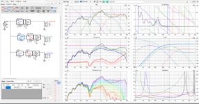
All done 4th order linkwitz at 2k
8" PS220 wideband woofer 1" RST28A metal dome tweet.
impedance curve no double hump.
waste of time to sim reflex.
Real life, is what it is.
Just a reflex.
2k crossover million miles away from the
reflex humpty dump.
accurate ZMA more important
for crossover network.
Can you help me understand why? Doesn’t the enclosure tool use complex models like ZMA and then adjust them according to the enclosure? Have I been messing up my sims this whole time?Dont need enclosure.
Just diffraction tool.
Yes. So how do the graphs look?
Way better!! I didn’t see the picture and thought nothing changed, my bad! Looks like a good start for sure. You want the power response to be flat, and that will take some tuning. An enclosure ought to bring up that bass, but how much is guesswork even with good simulations. You could try damping the midrange a bit, but otherwise an active design should be easy to mold to your specific room.
Yes I used the defrac tool and imported those results.
Should I make the speaker as narrow as possible in the defrac tool?
Should I make the speaker as narrow as possible in the defrac tool?
Something like that. If your DSP can handle more than crossovers, now you get to throw in PEQ’s and shelving. I recommend saving some slots for the room below 500hz when they’re built.
I have to ask, where was the mic icon when each driver diffraction was simulated? Was it center of each driver, or did you keep the axis the same? If the mic was centered on each driver, you need to take the distance from the center of the tweeter and apply it to the xyz on the crossover panel. Otherwise calculating spacing-based cancellations is hard in my experience and exaggerates how nice the finished product looks.
I have to ask, where was the mic icon when each driver diffraction was simulated? Was it center of each driver, or did you keep the axis the same? If the mic was centered on each driver, you need to take the distance from the center of the tweeter and apply it to the xyz on the crossover panel. Otherwise calculating spacing-based cancellations is hard in my experience and exaggerates how nice the finished product looks.
- Home
- Loudspeakers
- Multi-Way
- Critique my planned 3 way...