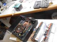
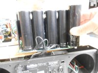
Hi Folks. The latest drama with a Crest CA-18 that I have attempted to tame for home theatre use; exploding main filter caps. The caps actually leaked and the fluid was absorbed by an insulating fibre board causing a short with spactacular results. I brought this problem on myself with the replacement of the cooling fans with slower, lower CFM units. I also installed a resistor in series with the fans. The amp heat sinks never really got hot but the caps are boxed in and glued together, shielding them from the limited air circulation.
My goal is to modify the fan control circuit to run slower at 75 degrees F and faster at 95 F
My goal is to modify the fan control circuit to run slower at 75 degrees F and faster at 95 F
Attachments

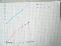
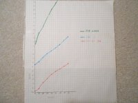
The fans are fed by an LM317 regulator, driven by Q3 (Q4 for the other channel) as shown on page 2. Q3 seems to have its effect reduced by the voltage divider R11 and R16. I have plotted the fan voltage and emitter voltage of Q3 with temperature.
Also the LM35 temperature sensor is connected to an LM358 op amp but there seems to be negative feedback introduced by R21 and R19 on page 5.
Any suggestions on how these circuits could be modified to increase the slope of the fan voltage change?
Thanks,
Peter
Also the LM35 temperature sensor is connected to an LM358 op amp but there seems to be negative feedback introduced by R21 and R19 on page 5.
Any suggestions on how these circuits could be modified to increase the slope of the fan voltage change?
Thanks,
Peter
Attachments
Hi Peter S,
A few questions:
Does a single LM35 sensor control speed for both fans? What maximum fan voltage would you like to produce? Both fans are driven at the same voltage? Would you delete the series resistors given appropriate fan voltages? Do you have a preferred voltage vs. temperature profile? (Piecewise linear segments would be best.)
Thanks.
If the heat sinks never got hot, the capacitors should not be heating up very much either. Ripple current is the only thing that heats up good caps. If the caps are leaky enough to heat up at all, or if the ESR has risen to the point where low ripple currents heat them up, they are bad anyway.
In normal operation, those amps blow like hair dryers. If you’re not doing that, you’re not hitting the caps that hard. 1/3 power at 4 ohms will exceed their ripple current ratings, yes, but HT use won’t even get close. They should last forever, even in relatively still air, unless they were crap to begin with. We know all the little IC electros on the boards are - they go out and it misbehaves (not usually fatal but an annoying maintenance item).
In normal operation, those amps blow like hair dryers. If you’re not doing that, you’re not hitting the caps that hard. 1/3 power at 4 ohms will exceed their ripple current ratings, yes, but HT use won’t even get close. They should last forever, even in relatively still air, unless they were crap to begin with. We know all the little IC electros on the boards are - they go out and it misbehaves (not usually fatal but an annoying maintenance item).
Hi BSST, there is an LM35 sensor on each of the two amp modules. The fans have two independent control circuits. I would remove the series resistors as this was a last resort solution after finding the new quieter fans were still too noisy. 6.2 Volts starts them from a stall so I would like the min voltage to be 7.5 V at approx 75 F. I would like the fan speed to increase faster with temp rise, maybe 18 V at 90 F.
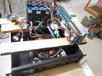
Thanks Sajti! This is the kind of solution I'm looking for. Rather than add a control circuit, I would like to modify the existing cicuit. What about shorting out R19 on page 5 (grounding the inverting input of the op amp) ? Could I then reduce the fan voltage by changing the ratio of R11 / R16 on page 2? I have had to make one harness extension to run the amp with some degree of access.
Thanks Sajti! This is the kind of solution I'm looking for. Rather than add a control circuit, I would like to modify the existing cicuit. What about shorting out R19 on page 5 (grounding the inverting input of the op amp) ? Could I then reduce the fan voltage by changing the ratio of R11 / R16 on page 2? I have had to make one harness extension to run the amp with some degree of access.
Attachments
Hi wg_ski, I suspect that the caps were crap to begin with. I am waiting for what will likely be more epay "crap" as replacement 18,000 ufd 75 V caps are not available in this size anymore...Strange, caps usually get smaller over the years. They may have tried to cram too much into that size can? I will deal with this later when (if) the 'fakes' arrive. Regarding HT use, most of the time this amp is overkill but I have seen Pink Floyd turn on the clip lights once or twice. The amp is driving 18" RCF drivers in JBL cinema sub cabinet copies.
Attachments
This is a fun challenge. 🙂
So you've ask for 7.5V at 75C, and 18V at 90C. That defines slope of 0.7V per degree C. A bit of algebra reveals a decriribing equation:
V= 0.7C-45, applying in the range between 75C and 90C. The attached sketch shows my suggested circuit.
Using R2 =249 and R1 =12k sets the LM317 output at about +7.5V when the opamp output is at 0V. Selecting D2 Zener voltage at about 16V will clamp the regulator output at about +18V max when the Adjust pin clamps through D1 and D2 to about 16.8V.
The opamp adjusts the nominal fan voltage between these two limits. Assuming a 16V Zener, setting R3 = 20k and R4 = 56.25k yields the -45 term in the above equation.
The LM35 delivers 10mV per degree C, so the opamp stage needs to generate gain of 7 at the fan drive, i.e. G = 1+ 56.25k/(20k//R5) =7.0. When you crank through the algebra, R5 turns out to be about 11.54k. I've calculated exact values for clarity, but 5% values are probably fine.
Attachments
Even having Pink Floyd light the clip lights occasionally is no big deal. In routine use I would flash them hard on every drum kick. Leave them on and the speakers will start to smell. Even then it doesn’t trip a mains breaker right away.
The long skinny form factor cap is hard to get these days. Even harder in snap-ins. Higher density caps always have a shorter rated service life than their larger counterparts. All 3 of mine were already on their second set of caps when I got them. Decommissioned from touring service, replaced with Labgruppens or something similar.
To lower the starting voltage, reduce R11 and R13, less initial multiplication of the 1.25 volt reference. Might have to iteratively adjust the slope with R19.
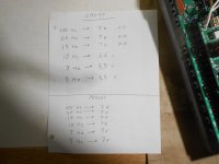
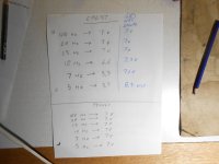
I put together the original fan driver circuit, but i got different results. Picture attached. Scaled from 20-80 degree centigrade.

Hi Folks, a little update. It took 10 weeks for the "18,000 ufd" caps to arrive from China. Sure enough, they only measure 15,000 ufd but the big deal breaker was the height. The ad claimed 35*118 mm but they are actually 35*130 mm. I wouldn't be able to get the lid on.
At the moment I have temporarily installed four 9,500 ufd caps for the low rails and I hear no audible hum. I will purchase 15,000 ufd caps from North American supplier and be happy about it.
Thanks for all your help with the fan speed issue. As per wg_ski, I shunted R11 and R13 with another 1k resistor, and left R19 on the preamp board as the stock value. The fans run at about 8 or 9 volts at room temp and is quite tolerable. I will measure the voltage increase with temp asap.
Thanks everyone for your input
Attachments

The last issue is the elimination of the the Crest's high pass filter if possible. I am using a Peavey GPS3500 for LF duty. I found a noticable difference in sound between the amps. The bass seems much deeper with the smaller Peavey. The Crest response starts to roll off right at 20 Hz while the Peavey has no high pass filter.
IC4B on the preamp pcb (page 4) is called the SERVO/HIGH PASS. Is there a simple way to eliminate the LF roll off?
I believe IGM stands for Instantaneous Gain Management but what the SERVO does is beyond me.
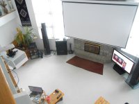
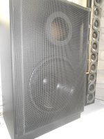
The subs pictured are copies of JBL cinema subs but made from 1" MDF. The drivers are 18" 1500 W RCF and the ducts' lower tuned peak is 19 HZ so I can definitely feel the difference.
Thanks again all.
IC4B on the preamp pcb (page 4) is called the SERVO/HIGH PASS. Is there a simple way to eliminate the LF roll off?
I believe IGM stands for Instantaneous Gain Management but what the SERVO does is beyond me.
The subs pictured are copies of JBL cinema subs but made from 1" MDF. The drivers are 18" 1500 W RCF and the ducts' lower tuned peak is 19 HZ so I can definitely feel the difference.
Thanks again all.
Attachments
I see the C8 as the only coupling cap. It set the rolloff to 7Hz approx. You can increase it. The servo was set to 0.3Hz (220k/2.2uF).
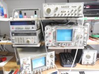
Hi Sajti, you were spot-on about the LF roll-off. I measured the Crest CA-18 and the Peavey GPS3500 just to make sure I was not imagining things. I bought a function generator for this purpose---any excuse to buy more Leader test gear! Both amps were measured into an 8 ohm dummy load and the P to P voltage was measured on a scope (DC coupling)
I calculated the Xc of the 2.2 ufd cap at 7 Hz and found it to be 10.3 k ohm. I confess to not understanding the circuit but wouldn't the cap that determines the roll-off be C 30 rather than C 8?
And what is a SERVO in this amp and how is it set compared to the High Pass point?
Thanks for your time and patience,
Peter
Attachments
Sajti, you were right again! I bypassed C8 with a 20 ufd polyester capand the response at 5 Hz actually rose above flat. Probably not good but you certainly pinpointed the cap to change. I will try 10 ufd next.
C8 is a film cap but could I use a good quality electrolytic?
Thanks!
C8 is a film cap but could I use a good quality electrolytic?
Thanks!
Attachments
- Home
- Amplifiers
- Solid State
- CREST Catastrophe