Yes, with the exception of only one power device pair instead of two and the lower supply voltages. And Elektor apparently had learned something as the opted to replace the 0.22R wire wound source resistors by five paralleled 1R carbon compound ones.
Best regards!
As the name suggest the mini version is a version with limited output power, obviously this is reflected in the OPS and PSU of the design.
The most imported however, these amps just work if build according the original design. Reported problems could be traced back to poor ground wiring, high-inductance source resistors and alternative component selection.
Below an amplifier I build around 1985 using 10 (ten) mini Crescendo's, 14 (fourteen) 4e order active Bessel filters, DC protection, soft start, and mains filters. Also a picture of one of the speakers I used to drive with it. I named them Amphion, a name later nicked by a Finnish manufacturer of inferior equipment.

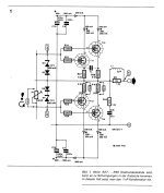
Elektor made a little Mod for the Crescendo Amp a bit later. I have to look in my book. I think it was an 100nf capacitor at the outputtransistors. I will make a scan...The book is called Audioschaltungsbuch.....from Elektor.
Surely i could built an Amp with more power....at first i make a test with my pcb. The 70 watt power at 4 ohm is enough power for me i think.
I use 2SK1058/2SJ62 on the board. I have a lot of these transistors (NOS). Exicon transistors i bought (2 Pairs) at Audiophonics, no costum duties as in GB. The old Hitachi TO-3 i have also in stock, have to count......
I have also bought at Albs, a matched pair 2SK135/SJ50. 0 mV offset was the result. But you are right, these transistors became very expensive. 50 Euro and more for one non matched pair...
To many projects.... 🙂
I have made to many pcb's....Blame ST MKII Supercharged, Apex FH9 XRK Mod, NAP 250, NCC200
I toss a coin to figure out wich Amp will be the first....
Greets
Peter
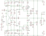
To remove any trouble two 33pF capacitors should be connected from the VAS output to its inputs to implement
a proper miller compensation, natively they did rely on the fets input capacitance to get a random shunt compensation
that doesnt work well if at all, hence why some people increase the VAS capacitive loading by connecting capacitors
from gates to source, wich is a dubbious solution.
If one use high supply voltages then best is to use 2SA992/2SC1845 wich are 120V but have also different pinout,
so beware if you do such a modification.
Also using 10k resistances to feed the cascode zeners require 0.5W resistances if not more, better use 33k or even 47k ones.
This way, a TMC compensation can also be implemented wich should yield a little better THD numbers,
but the implementation in the pic below is straightfoward and should tame any oscillations,
just make sure that the capacitors have at least 200V capability, if you cant find such high voltage caps
you can use two 100V 68pF capacitors in serial for each branch.
but the implementation in the pic below is straightfoward and should tame any oscillations,
just make sure that the capacitors have at least 200V capability, if you cant find such high voltage caps
you can use two 100V 68pF capacitors in serial for each branch.
Attachments
Glad to hear there are options. Although there are enough genuine parts in my stashes presently 😊 .If one use high supply voltages then best is to use 2SA992/2SC1845 wich are 120V but have also different pinout,
so beware if you do such a modification.
Anyway, a voltage rating of just 120 Vdc wouldn't be enough with an original Crescendo, whose supply comprises a 50-0-50 Vac power transformer, hence 70 Vdc per rail at idle at least.
Yes, that's the modification ELEKTOR suggested in the »Nachlese« (= aftermath) some months later.I remembered that wrong. The Mod only is helpful if you are using wire resistances at the output. Then, to avoid oscilations, one 1nf capacitor should be used.
See picture
Best regards!
^^ The Nederlandse version of the above mentioned modification. Did not need it myself, but might be useful to have it at hand.
And the Hitachi data sheets
And the Hitachi data sheets
Attachments
Last edited:
Glad to hear there are options. Although there are enough genuine parts in my stashes presently 😊 .
Anyway, a voltage rating of just 120 Vdc wouldn't be enough with an original Crescendo, whose supply comprises a 50-0-50 Vac power transformer, hence 70 Vdc per rail at idle at least.
Yes, that's the modification ELEKTOR suggested in the »Nachlese« (= aftermath) some months later.
Best regards!
Since the bases of the differentials transistors are tied to ground DC wise the emitters will be at about 0V as well,
so they have to sustain only a rail max voltage, so 120V is enough and much better than the original 65V Vce BC546/556.
In the schematic i posted these are 2SA872/2SC1775 wich are only 90V but in my builds of such symmetrical
differentials i used 2SA872A/2SC1775A wich are also 120V but have only 0.3W TDP capability.
FWIW i used such a symmetrical differential with those transistors for the differentials but also for the VAS with
a 2.5mA current and driving 3 pairs of 2SJ48/2SK133, wich are the 120V version of those old laterals, the amp was used
for PA purpose with a 2 x 43V toroid for roughly 15 years and it proved very reliable despite 4R loading and no forced cooling.
- Home
- Amplifiers
- Solid State
- Crescendo 1982 PCB-copper thickening