Sorry to answer so late...
All I have are copies from copies from the eighties - a little awkward to read indeed. Sorry for that. I try to scan my data again for you. Please contact me via mail.
- the files are a bit too large to post them here.
All I have are copies from copies from the eighties - a little awkward to read indeed. Sorry for that. I try to scan my data again for you. Please contact me via mail.
- the files are a bit too large to post them here.
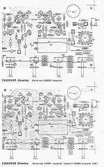
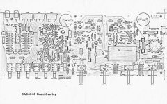
ok, here are the uploads - they have been shrinked, but I hope you can read it. Please ask me for any further details. I also still have spares 🙂
If the output transistors are blown, it is quite likely the the drivers (if non darlington) and the class A stage is possibly blown also. Please check carefully.
If the output transistors are blown, it is quite likely the the drivers (if non darlington) and the class A stage is possibly blown also. Please check carefully.
Attachments
How similar is the 4040 to my 4330. Just looking at schematics to understand some basic amp theory and tradeoffs.
Bit off-topic maybe, but I went for an interview with Michael Creek around 1980. He wanted someone to do a FM tuner, which sadly wasn't my field. I was more interested in balanced phono stages at that time.
In those early days he and his German colleague worked from his back room in his house in South London. He kindly swapped schematics with me, and we had an enjoyable discussion of ideas. He told me one of his neatest accomplishments was to get each component doing lots of things, thus keeping circuits simple! Top man! 😎
In those early days he and his German colleague worked from his back room in his house in South London. He kindly swapped schematics with me, and we had an enjoyable discussion of ideas. He told me one of his neatest accomplishments was to get each component doing lots of things, thus keeping circuits simple! Top man! 😎
I visited this place on business, L&N Radio - Electronic Manufacturing Sub - Contractor in the late 80's or very early 90's and they were building Creek amps.
Would anyone happen to have a 4330 schematic? I guess I should not be surprised that the photo looks deceivingly simple. Second guess is it is a class AB single output design.
http://www.diyaudio.com/forums/solid-state/9286-creek-4330-rotel-ra-971-schematic-ca-a500-p500-2.html
maybe this is still valid?
maybe this is still valid?
Thank you, lokh.
I found out that the output transistors are very expensive. So indeed, i have to find out first if the other transistors are ok. Thanks for the prints anyway.
I found out that the output transistors are very expensive. So indeed, i have to find out first if the other transistors are ok. Thanks for the prints anyway.
Hi Martin!
Thanks for this schematic but I did a mistake. I requested the s1 model but in fact, I have 2 models: s2 and s3 nor s1.
If you have these ones too, thanks in advance. Specially, the s1 model witch is the one in trouble. I have big "ploc" at startup and when powered off.
Stef...


A very fine sounded amp, if one have a correct dimensioned external (outdoor) power supply include choke. The genuine power supply, especially the caps are too small for proper sound.
A Question: What is the correct term in the colloquial english language for the heatsink assembly aluminium block, that press the power transistors on the surface from the heatsink - also to find inside of Mission Cyrus about follow link?
http://ftbw.de/files/resources/Cyrus_II_inside.png

Would need to see the circuit to tell you that...
I see the transformer says "220Vac". Mains in the UK can reach as high as around 256 on a good day 🙂 I don't know why it would say that but for a UK product that is wrong and taken at face value means the DC rails in the amp could be somewhat higher than expected with possible problems due to over running parts/caps and consequent increased power dissipation.
I see the transformer says "220Vac". Mains in the UK can reach as high as around 256 on a good day 🙂 I don't know why it would say that but for a UK product that is wrong and taken at face value means the DC rails in the amp could be somewhat higher than expected with possible problems due to over running parts/caps and consequent increased power dissipation.
RP1 and RP2 probably are the resistors for the power regulators for the input stages. If you have a too high voltages (because of highish mains supply) they have to work hard and get very hot.
Creek CAS4040 S3b
Hi,
I need schematic for Creek CAS4040 S3b version. Serial No: A 026975
It has BDW93C and BDW94C in output, three 1N4148 between BASE. BD139 and BC639 before them. No potentiometer for idle current.
Thank you.
Hi,
I need schematic for Creek CAS4040 S3b version. Serial No: A 026975
It has BDW93C and BDW94C in output, three 1N4148 between BASE. BD139 and BC639 before them. No potentiometer for idle current.
Thank you.

Addendum: the spec for the original darlingtons can be found here:
BDT65 pdf, BDT65 description, BDT65 datasheets, BDT65 view ::: ALLDATASHEET :::
I'm guessing the BDW93C/94C pair are preferable as replacements?
BDT65 pdf, BDT65 description, BDT65 datasheets, BDT65 view ::: ALLDATASHEET :::
I'm guessing the BDW93C/94C pair are preferable as replacements?
- Status
- Not open for further replies.
- Home
- Amplifiers
- Solid State
- Creek CAS 4040 amp schematic