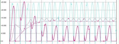
and here is the graph of the results
As you can see this is a 12V supply
The significant bit is that the wobbly pink line at the bottom does not quite get to zero.
If it does the 1st inductors have to be bigger.
But the higher the current draw, the smaller the 1st inductor can to be to achieve this.
If you are planning that the bias is going to be variable you might need a snubber cct between the diodes and the L1 cos if the current does dip below the zero line there will be serious ringing in the chokes
The second LC element really smooths out the DC ripple.
I hope that this may help you a bit with your design
mike
Attachments
BUT......
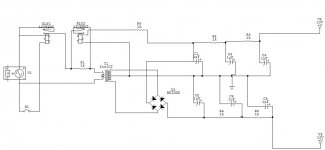
for CLC regulation for 12V DC the AC supply would have to be about 9V, perhaps a little more
for this LCLC cct the AC supply is 27V AC for a 12V DC rail
I'm not sure if this has already been mentioned but it might mean that the trannies that you have may not be suitable for LCLC in which case CLC with a snubber cct across the secondaries will still sound pretty good
over & out
mike
Magura said:I am aware of the issues regarding LC filters, but so far I have seen little evidence that a LC is better than a CLC, it's just more trouble. Have anybody actually made a test of a LC VS. a CLC?
I agree the theory is correct, but I am still to see one of my PSU's pollute the mains to a degree where the regular mains pollution would not set the "pollution floor".
Besides that a LC filter would require a substantially bigger inductor, which would mean that it would be either very expensive or very high DCR.
I think John Curl will know he said he was designing supplies like this recently - mine is still only in virtual reality. I will probably try these comparisons sometime this year.
Yes OK perhaps you would have to clean up the mains to notice any difference
From my similation you can see that the inductors in the LC part are about the same as the inductors in the CLC part.
mike
What is so different with putting the capacitor in front of the inductor (CLC) as opposed to putting the inductor infront of the cap (LC)?
I know what's going to happen with SPICE,,,,,as soon as I figure it out, the trial will expire!!!
I'm confused with the science here. 😕 Will SPICE produce a scope image of my virtual PSU?
Why would an inductor "keep the tranni flowing"?
😕 😕 😕
I know what's going to happen with SPICE,,,,,as soon as I figure it out, the trial will expire!!!
I'm confused with the science here. 😕 Will SPICE produce a scope image of my virtual PSU?
Why would an inductor "keep the tranni flowing"?
😕 😕 😕
Clarkcr said:
Why would an inductor "keep the tranni flowing"?
Basic electronics 101... Inductors oppose a change in current.
If you are not intimately familiar with basic principals are you sure you should be designing power supplies with lethal voltages?
I know 120VAC is barely lethal, but it is nonetheless.
Clarkcr said:What is so different with putting the capacitor in front of the inductor (CLC) as opposed to putting the inductor infront of the cap (LC)?
Why would an inductor "keep the tranni flowing"?
Think of a coil as the electrical equivalent of inertia, or mechanical
mass. Since the draw on a transformer is being rectified to
DC with nice big capacitors, you will see that the current flow is
during a relatively short spike at the top of the voltage waveform
coming out of the transformer. If you put a coil in series with the
transformer, you broaden out the spike and improve what is
known as the "power factor". This is good, but the downside
is that an inductor in series with the transformer windings is
a series impedance which reduces the available voltage in most
applications.
The upside is that such an inductor can be used to relatively
losslessly attenuate the output voltage on a transformer,
particularly with constant draw type circuit (hint: Class A)
😎
What did your Alephs have in them? LC....CLC.....CRCRC.... Did you use analytical software like SPICE to get close to what you wanted on the rails, then fine tune it with a trial and error approach?
I have the whole PSU built in SPICE....about to start a help thread for inputing values and appying voltages.
Thanks for all the great hlep and encouragment.
C
I have the whole PSU built in SPICE....about to start a help thread for inputing values and appying voltages.
Thanks for all the great hlep and encouragment.
C
The production Alephs were a simple C; no L or R. Nelson is not fond of simulation programs and I doubt that he made an exception in this case.
That's not to say that you can't build a higher performance supply if you want to. That's part of the charm of DIY--the ability to max out a design. Flog the thing to within an inch of its life.
Grey
That's not to say that you can't build a higher performance supply if you want to. That's part of the charm of DIY--the ability to max out a design. Flog the thing to within an inch of its life.
Grey
BTW, what is the largest-value low-cost air-core inductor available off-the-shelf? This would be useful for quickly and easily experimenting with (or implementing) choke-input power supplies, methinks.
As an example, for low-power applications, J.W. Miller's 4652 is a 1000uH phenolic-core coil (IDC 160mA), and costs about $1.50 at Mouser.
Does anyone know of similar off-the-shelf low-cost air-core inductors, but of larger value?
TIA, jonathan carr
As an example, for low-power applications, J.W. Miller's 4652 is a 1000uH phenolic-core coil (IDC 160mA), and costs about $1.50 at Mouser.
Does anyone know of similar off-the-shelf low-cost air-core inductors, but of larger value?
TIA, jonathan carr
Clarkcr said:I have the whole PSU built in SPICE....about to start a help thread for inputing values and appying voltages.
C
Great - can you put a link to it here when you post it.
cheers
Mike
mikelm said:
Great - can you put a link to it here when you post it.
cheers
Mike
Here it is. I spent the better part of an hour last night trying to change values to no avail. I'll have to call the manufacturer today and learn how. I'm baffled.
Attachments
Nelson Pass said:Think of a coil as the electrical equivalent of inertia, or mechanical mass. ...
😎
Books always say RC and LC filters. The letters R and L are always positioned before the letter C. In addition say that R and XL are to be greater than Xc. If so, the R and L are kind of shock absobers against the considerable (electrical equivalent) inertial mass?
----------------
Clarkcr, excuse me, but do you need a P(izza)H(ut)D(elivery)...???
rabstg said:
Basic electronics 101... Inductors oppose a change in current.
If you are not intimately familiar with basic principals are you sure you should be designing power supplies with lethal voltages?
I know 120VAC is barely lethal, but it is nonetheless.
If you see a large plum of smoke to the East, you might suspect is was me. Then again, you could come over to the house and help me. Or take me to the hospital....one or the other!!! 😉
C
jcarr said:BTW, what is the largest-value low-cost air-core inductor available off-the-shelf? This would be useful for quickly and easily experimenting with (or implementing) choke-input power supplies, methinks.
As an example, for low-power applications, J.W. Miller's 4652 is a 1000uH phenolic-core coil (IDC 160mA), and costs about $1.50 at Mouser.
Does anyone know of similar off-the-shelf low-cost air-core inductors, but of larger value?
TIA, jonathan carr
I found one in Mouser this morning I think I'm going to get for the heck of it. It's a Common Mode air-core inductor, with min inductance of 2.0mH and rated at 7.5 amps. max impedance of .02 ohms. They're only $4.75 each so why not? I'll put one on each side in series before the caps and see what happens. Maybe I'll wait until I figure SPICE out......they have an engineering developemnt kit for $33....with all different values looks interesting. The other values are 4mH, 8mH, 16mH.
Thoughts?
C
Hi Clarkcr,
What is the Mouser part number? Something doesn't seem to add up for your 2.0mH inductor. The DCR seems way too low.
Graeme
What is the Mouser part number? Something doesn't seem to add up for your 2.0mH inductor. The DCR seems way too low.
Graeme
jcarr said:Does anyone know of similar off-the-shelf low-cost air-core inductors, but of larger value?
Jonathan, it seems to me you're looking to speaker crossover air coils if you want higher values with sufficient current carrying capacity.
Anyone of you SS types try Jensen air coils as power supply inductors? They work mahvelously in speakers. I suspect they'd work equally well in a power supply ... low dielectric absorption, nicely damped, good quality copper. I'd use them for tubes but their voltage rating is about 100V (A or DC) IIRC.
For experimenting purposes, a roll of magnet wire should be cheap and effective, and wound with a certain precise randomness to boot.
I believe that Nelson is fond of the Erse steel cored coils for power supplies. Low DCR, high current capacity, Don't saturate up to about 6-7 amps I think he said, with 14 ga wire.
Yup, Common mode inductors won't work
Yup, Common mode inductors won't work
- Status
- Not open for further replies.
- Home
- Amplifiers
- Pass Labs
- CRCRC vs. LCLCLC which is better and why?