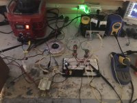
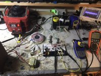
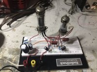
I was going through a box of random tubes, and I found a pair of EL84s. I decided to try building a single ended amp with them on a breadboard. For the OPT, I rewound a 120-12 volt line transformer until the primary read around 5.5K with an 8 Ohm load on the secondary. The amp does seem to have some ringing at high frequency, would this be why?
My power supply is just a dual 120 volt to dual 30 volt transformer run with the 30 volt windings in parallel, fed from a variac, and the 120s in series. This allows me to adjust the B+ to about 250 volts.
The gain stage is a 6C4 running at 180 volts of B+.
Surprisingly, this amp sounds pretty good in my opinion, aside from the HF ringing, which I need to look at into a dummy load with the scope tomorrow.


Please post a schematic.
Ringing?
If you can hear the ringing, and are not looking at it with a scope,
It is more likely oscillating.
"Ringing" is a response to a square wave, or to clipping.
It is not found when listening to ordinary music, unless your amp is at the ragged edge of oscillation.
Ringing?
If you can hear the ringing, and are not looking at it with a scope,
It is more likely oscillating.
"Ringing" is a response to a square wave, or to clipping.
It is not found when listening to ordinary music, unless your amp is at the ragged edge of oscillation.
I'll post a schematic soon. Interestingly, I hooked it up to my dummy load resistor, and looked at it with the scope, and it looked quite good, no ringing or oscillating at all. Strange, I wonder if what I was hearing is an artifact of interference or my speaker.
I tried using toroids in a parafeed headphone amp, and I got the same kind of high frequency problems. I swapped in a Lundahl LL1689 and the problem went away.
Other than the absence of the grid stoppers (EL84 needs one, not sure about 6C4) there's nothing wrong with the schematics.
Could that be purely mechanical issue? Tubes seem to be literally floating in the air, you might get some mechanical resonance.
Could that be purely mechanical issue? Tubes seem to be literally floating in the air, you might get some mechanical resonance.
Huh, absolutely didn't think about that. The tubes are just held up by their solid core leads in the breadboard. I'll add a grid-stopper to the EL84.
Thanks!
Thanks!
The EL84 has about 10mA/V. Multiply that times 5000 Ohms, that stage gain is about 50.
The 6C4 gain in that circuit may be about 15. That means the total gain is about 750.
If the input stage grid circuit and output stage plate circuit wiring is close, it can oscillate.
A loudspeaker load plus the output transformer could easily have an impedance range of 2000 to 10000 Ohms, or even higher ratio.
And the loudspeaker and output transformer will have resonances, which could promote oscillation.
With the amp as you have it now, the damping factor is less than 1.
With the loudspeaker as the load, look at simple music signals at moderate volume with the scope.
A solo instrument should have simple waveforms, not added oscillation.
You can disconnect the 100 Ohm screen resistor from B+, and connect that free end to the EL84 plate. That is Triode wired mode.
These will be reduced: gain and power.
But the damping factor will go up, and the distortion will go down.
Just an easy thing to try.
If there is any ringing with a loudspeaker it probably is the interaction of the high output impedance and the reactive load. Even if it doesn’t oscillate outright you will have audible effects that may sound like ringing. With a dummy load it will behave better than with a speaker. Add a zobel and any ill effects at high frequency should go away. The bass resonance you’re stuck with, unless you triode-strap it. Single ended pentodes were often used where the rising HF and spike at fs were useful, such as table radios and TVs where the speaker’s response was limited and would benefit from the free smiley-face EQ.
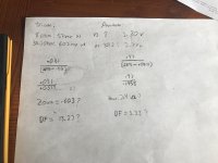
Triode wiring sounds way better for sure. I'm going to see if I can measure the output impedance for triode and pentode mode and do the math to figure out the damping factor for each.
There's some calculation mistake for the triode mode - the V1 and V2 shown make for 2.72 ohm output impedance (which seems appropriate)
Pentode mode calculations look ok - maybe measurements gone wrong?
Pentode mode calculations look ok - maybe measurements gone wrong?
I can try measuring again. I was using my scope across the power resistor and looking at the RMS voltage while feeding in a 1khz sine wave at a fixed level. I looked at the article rufus linked, but I can't do that because it requires measuring voltages no load, which you can't do on a tube amp, correct?
Thanks!
Thanks!
No, you don’t want to run with no load, but you can use a lighter load, such as 20 or 30 ohms. The resulting data can still be used to calculate output impedance.
You should be able to get a rough idea by dividing the plate resistance from data sheet curves by the transformer ratio (5000/8). In any case, do everything at midband where the reactive effects in the transformer are minimal. Unless you *want* to do vector measurements.
There may not be much if any audible difference between a damping factor of 20 and 20,000, but there sure as hell is between 2 and 0.2.
Half-correct 😎I looked at the article rufus linked, but I can't do that because it requires measuring voltages no load, which you can't do on a tube amp, correct?
You can do it in the triode mode, but definitely don't do that in the pentode mode.
But the formula in your post #12 is correct, you can use it.
According to the formula that wg_ski gave, I divided 40k plate resistance by the impedance ratio, and got a output impedance of about 58 ohms for pentode mode, and for triode mode, with a plate resistance of around 2k, I got an Output impedance of 2.9 ohms.
I tried my math a couple more times, but I couldn't get the same results with the voltages I measured across my resistors on the above piece of paper, or even when I tried it again with some different resistors. If the 58 ohm and 2.9 ohm numbers are anything to go by, Pentode mode has a DF of .137 and triode mode has a DF of 2.7
Do these numbers seem any more reasonable?
Thanks!
- Home
- Amplifiers
- Tubes / Valves
- Crappy EL84 SE Amp

