Hi Kevin,
Check the zener diodes on the gates and make darn sure those resistor connections are good. Same goes for the bias circuit mounted with three wires that go to the main PCB. It's a Vbe multiplier, nothing complicated there. Then make sure the bias generator power supply is okay. There are two resistors off the main rails (run hot-ish) under the PCB I think. They connect to a pair of zener diodes ans a pair of 10uF caps each. This is located near the DC power supply rail fuses. Just make sure all that stuff is alive.
You will not see any bias current (or shouldn't!) until the small relay closes after 5 minutes (a while +/- 2 minutes). Then the voltage amp is also connected to the output stage.
-Chris
Hi John,
You can't implement that output stage as you've drawn it. The On Semi parts are BJT types firstly, so nowhere near a 1:1 swap. You will need a bias control circuit (there is one already, but the thermal gain may be off). You also need a buffer between the voltage amp and the outputs. Tube outputs are not going to like a highly variable input impedance like one presented by a standard triple either.
I used a power diamond buffer. When you've got it working right, the best sound quality I've heard. When it isn't working right, it sounds "off". Also, it will current limit depending on how you set it up. The core of my output stage is a diamond buffer, but there is more and I'm not done yet. The best part is that my worst case DC offset is +/- 35 mV - without adjusting anything! 🙂
As for the original parts from IRF, they have gone up a lot. So ... use a more current substitute from them. Those parts are admittedly long in the tooth by now. So, just find a modern substitute.
As for the plastic TO-204 devices, I mentioned recently (A couple posts ago) what you need top what for, and where I know there is a problem. Remember, I set up an alternative BJT output stage on the same heat sinks. I used the same case style as the originals. You have to love On Semi for making the same number available in more than one package.
-Chris
Your diamond buffer sounds nice.
Oh, yeah I used MOSFET symbols on the outputs by accident. I just used a compound emitter follower push pull output stage, except the I used IRF520/IRF9520 Mosfets instead of BJTs at the input. I don't understand what the problem with it is. Why would Elliot's bias circuit have problems biasing the IRF520/IRF9520? or driving one complementary pair of Mosfets?
The BJT's are just biased by the 6.8 ohm resistors, and I checked the datasheet on the BJT's to make sure there was enough current drive for full output power. I can't say the circuit will work right with those exact values but I think the topology is okay. But, I've never built an amp before.
Well, I'll have to sim it and prove that it works or doesn't.
John
Last edited:
Okay, I simmed my output stage mod and it does work. Sorry, for posting the confusing schematic last time. I used MJL21193/MJL21193 BJT parts since I had those models. I can't say it works great yet, just about twice the distortion On-Semi published in their data sheet of 0.8% THD for unmatched pairs.
My distortion is 1.5% THD. Still maybe with some work and the right transistors it might be good ... I wouldn't know.

But it works in sim, and so there it is, working ... 🙂
My distortion is 1.5% THD. Still maybe with some work and the right transistors it might be good ... I wouldn't know.
But it works in sim, and so there it is, working ... 🙂
Attachments
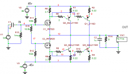
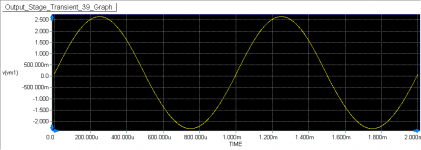
Opps, I forgot the 2uF coupling cap between the gates of the mosfets. Now the distortion is way lower at 0.01%!
Well this is a sim, but that's good isn't?
Well this is a sim, but that's good isn't?
Your diamond buffer sounds nice.
Oh, yeah I used MOSFET symbols on the outputs by accident. I just used a compound emitter follower push pull output stage, except the I used IRF520/IRF9520 Mosfets instead of BJTs at the input. I don't understand what the problem with it is. Why would Elliot's bias circuit have problems biasing the IRF520/IRF9520? or driving one complementary pair of Mosfets?
The BJT's are just biased by the 6.8 ohm resistors, and I checked the datasheet on the BJT's to make sure there was enough current drive for full output power. I can't say the circuit will work right with those exact values but I think the topology is okay. But, I've never built an amp before.
Well, I'll have to sim it and prove that it works or doesn't.
John
I read this topic from beginning because I have a Counterpoint SA100 to work for. Just two question to ask. Why do you want to connect the collectors of output transistors to be the output? How can you adjust the bias? Thermal runaway is an important issue for the BJT; you must think about it.
I read this topic from beginning because I have a Counterpoint SA100 to work for. Just two question to ask. Why do you want to connect the collectors of output transistors to be the output? How can you adjust the bias? Thermal runaway is an important issue for the BJT; you must think about it.
Well, I did that because Elliots bias arrangement was designed for a Mosfet output stage. I think that's what Chris was getting at earlier when he commented on my circuit at first. This output stage allowed me to use only a single complementary pair of Mosfets, which greatly helps the ability of the tubes to drive the gate capacitance.
Biasing this circuit is the same as biasing a common emitter follower output stage. Increasing the voltage between the gates of the Mosfets increases the bais current through the Mosfets, and this increased the current through the 3.7 ohm resistors (in parallel with he Base-Emmiter of the BJTs) and that increases Vbe and the current through the output BJTs.
Elliot used a Vbe multiplier to set the bias, and that should work fine for this circuit.
The only way I saw to use BJTs for the output stage was to have Mosfets driving the BJTs. The other option would be to use a darlington configuration where the Mosfet drives the base of the BJTs.
I like this circuit cause the Mosfets are kind of in control as the output just follows the sources of the Mosfets. I also read in John Lindsey Hood's book, "The art of linear electronics," that this output stage is more immune to thermal runaway that the darlington configuration, though I'm not sure why.
I MOSFETs are biased fairly high and the power dissipated by the mosfets doesn't change much. That helps with thermal runaway and they will have their own heatsink which helps (assuming I build this ... I'm still investigating options).
I know thermal runaway is a problem and I may even add a thermistor to the bias circuit to keep that in control.
I also plan to bias the output transistors at about 200-250mA per pair, which would mean that the heatsink would be dissipating 45 watts total at idle.
If the temp is too high I'd have to, bias slightly lower.
Anyway, that's sort of the plan. I'm sure I'll run into all kind of problems when I start wiring it up. So, that makes feel bad and not so anxious to jump into this.
But, I'm really interested in trying this. I find the MJ15001/MJ15002 model well, though I haven't checked out the data sheet yet.
I'm looking for a pretty flat beta in the power range they'll be operating in, and low capacitance.
Hi Kevin,
Check the zener diodes on the gates
I've been looking into this...as there seems to be a difference between the zener diodes and a regular diode. I had to check some standard diodes previously on the amps I was working on a few years back. Is is safe to say that I only need to know if the zener diodes are opened up or shorted? So I should get away with lifting one leg of the diodes and measuring resistance in both directions to determine if I get resistance one way and infinity in the other? This won't give me its voltage level, is that a concern?
and make darn sure those resistor connections are good.
I checked continuity on all the work I did with the gate resistors throughout the protection circuit to the diodes, gates and through to the PCB with my meter.
Same goes for the bias circuit mounted with three wires that go to the main PCB. It's a Vbe multiplier, nothing complicated there.
OK...are you referring to continuity to the pcb through the leads mounted to the D, G and S tabs? I tried reading up on the Vbe multiplier and bias circuits in general...it basically sounds like a way to regulate voltage to create an ideal operating range for the transistors? Without the understanding of what happens in these types of circuits I feel like I'm groping in the dark.
Then make sure the bias generator power supply is okay. There are two resistors off the main rails (run hot-ish) under the PCB I think. They connect to a pair of zener diodes ans a pair of 10uF caps each. This is located near the DC power supply rail fuses. Just make sure all that stuff is alive.
OK...sounds like driving directions a little...LOL. I'm the type of person that turns left at the big rock and then right at the two oak trees, so this might work for me. I will have to get the board out of the case. I've been considering that requirement since the leaky caps in the center of the pcb will have to also be replaced. I think since the connections running from the main power supply caps and all the grounds in the front of the case appear to attach via spades, the best way to do this is to label and remove them all and then release the heat sinks from the case. I should be able to then release the pcb from the case and carefully remove it so I can work from the bottom as needed.
You will not see any bias current (or shouldn't!) until the small relay closes after 5 minutes (a while +/- 2 minutes). Then the voltage amp is also connected to the output stage.
Getting ahead of me here. Are you talking about after I actually check everything, replace the mosfets and try and start it up for the biasing procedure?
Kevin
-Chris
Hi Kevin,
-Chris
You can just measure each way on each zener diode. They will test very similarly to a regular rectifier diode if they are good. If you passed about 1 mA through the diode (A half decent diode test function, 1 mA is common), you would see that a zener diode has 700 mV and change in the forward direction, and open in the reverse direction. If your current supply was high enough, you would be able to measure the reverse voltage drop of the zener as well. For now, just like a rectifier (~550 mV-ish) but a little higher forward "resistance".So I should get away with lifting one leg of the diodes and measuring resistance in both directions to determine if I get resistance one way and infinity in the other? This won't give me its voltage level, is that a concern?
Just make sure nothing breaks free while you are powered up. An open gate will generally cause massive current flow. You don't want this to happen.I checked continuity on all the work I did with the gate resistors throughout the protection circuit to the diodes, gates and through to the PCB with my meter.
No. There is a small transistor (metal case, TO-18) attached to the heat sink in the center area. There is a three conductor ribbon cable connecting this to the main PCB. If you disassemble the unit (as you will), these and the other soldered wires tend to break free. Of course, all the amps I see have been played with first. Just assume this is the case. Take pictures and mark the white wires so you know where they went. There should be labels on the PCB, but why take chances?OK...are you referring to continuity to the pcb through the leads mounted to the D, G and S tabs?
Take a picture and post it once you're ready to go in there.OK...sounds like driving directions a little...LOL.
Yes. I'm planting the seed of the things you need to watch for.Getting ahead of me here. Are you talking about after I actually check everything, replace the mosfets and try and start it up for the biasing procedure?
-Chris
Hi John,
Okay, that will work I guess. Given the proper component values are used.
200 ~ 250 mA bias is too high, and so is 45 watts!!! Do you have any idea how much heat that is? With BJT transistors, there is a "happy spot" for bias current. If anything, this is your chance to reduce the running temperature of this amp (strongly positive turn of events!). I feel that 100 mA is too much, 50 mA might be more in keeping with the size of the heat sink. The fact that you are not using overall feedback demands higher than normal bias current. With feedback, you can really cut the current back.
You may find some mosfets you can use as drivers that have a more constant (and lower) gate charge requirement. That will really help the tubes drive this. Remember, we are talking about dynamic signals, not DC signals. The input impedance isn't nearly as high for mosfets when you get into the higher frequencies. I prefer a 100% BJT output stage over mosfets in this situation, but it's your amp after all.
Use current sources. You can scope out a few threads on various diamond buffer implementations on this site. There are some headphone amps too. Look at the levels of distortion people are getting - without any feedback! This is a natural. Although, you look like you're on the path to getting something working. Should be interesting.
-Chris
Okay, that will work I guess. Given the proper component values are used.
200 ~ 250 mA bias is too high, and so is 45 watts!!! Do you have any idea how much heat that is? With BJT transistors, there is a "happy spot" for bias current. If anything, this is your chance to reduce the running temperature of this amp (strongly positive turn of events!). I feel that 100 mA is too much, 50 mA might be more in keeping with the size of the heat sink. The fact that you are not using overall feedback demands higher than normal bias current. With feedback, you can really cut the current back.
So, tell us what the expected distortion is with matched pairs then ... The ratio is about 10:1, and we are talking about no feedback here. That is pretty excellent if you ask me. I see no reason why you shouldn't match the outputs. The SOA on the MJL21195 & MJL21196 is a little higher, so go with those.I used MJL21193/MJL21193 BJT parts since I had those models. I can't say it works great yet, just about twice the distortion On-Semi published in their data sheet of 0.8% THD for unmatched pairs.
You may find some mosfets you can use as drivers that have a more constant (and lower) gate charge requirement. That will really help the tubes drive this. Remember, we are talking about dynamic signals, not DC signals. The input impedance isn't nearly as high for mosfets when you get into the higher frequencies. I prefer a 100% BJT output stage over mosfets in this situation, but it's your amp after all.
Diamond Buffer!The only way I saw to use BJTs for the output stage was to have Mosfets driving the BJTs. The other option would be to use a darlington configuration where the Mosfet drives the base of the BJTs.
Use current sources. You can scope out a few threads on various diamond buffer implementations on this site. There are some headphone amps too. Look at the levels of distortion people are getting - without any feedback! This is a natural. Although, you look like you're on the path to getting something working. Should be interesting.
-Chris
Hi cfan,
I'd strongly recommend you have an expert look after your SA-100. For these, if you want to retain the original output section, there are three circuit boards I designed to go in there. If you are changing to the BJT style output stage, three PCBs again are added, one is the same as in the mosfet case. I'm not finished designing these yet, but I'm just trying to let you know there are a number of issues to address. You do have PCB damage due to heat, I know this already. Your heater power supply is probably toast by now. There is a lot of stuff that runs too darn hot in those amps.
Remember, your amp runs hotter than the SA-12. You have the same, and more problems, plus your problems are more severe than what the SA-12 owners have.
-Chris
And the few extra volts make this amp an entirely different kettle of fish. You have more serious issues that directly affect the long term reliability. If you don't look after them, your amp will never be reliable.I read this topic from beginning because I have a Counterpoint SA100 to work for.
I'd strongly recommend you have an expert look after your SA-100. For these, if you want to retain the original output section, there are three circuit boards I designed to go in there. If you are changing to the BJT style output stage, three PCBs again are added, one is the same as in the mosfet case. I'm not finished designing these yet, but I'm just trying to let you know there are a number of issues to address. You do have PCB damage due to heat, I know this already. Your heater power supply is probably toast by now. There is a lot of stuff that runs too darn hot in those amps.
Remember, your amp runs hotter than the SA-12. You have the same, and more problems, plus your problems are more severe than what the SA-12 owners have.
-Chris
Anatech said:200 ~ 250 mA bias is too high, and so is 45 watts!!! Do you have any idea how much heat that is?
45 watts is less than a First Watt F5 (68 watts) at idle, but I guess these heat sinks aren't really that big. I guess that could get pretty hot, so I'll start with a low bias. From many peoples accounts you have to listen to get the bias just right, so I'll do that. I have a distortion analyzer too, so I won't be lost in the woods.
Anatech said:So, tell us what the expected distortion is with matched pairs then ... The ratio is about 10:1, and we are talking about no feedback here. That is pretty excellent if you ask me. I see no reason why you shouldn't match the outputs. The SOA on the MJL21195 & MJL21196 is a little higher, so go with those.
Yes, I saw that on the data sheet for the BJTs you used. The distortion for a beta matched pair was about 0.08%. I plan on matching the transistors.
The 1.5% distortion was because I forgot the coupling cap between the mosfet gates. In spice sims the distortion I get now is about 0.01% at one watt, and 0.02% at 14 watts baised at 250mA, with no feedback. I can turn down the bias but distortion goes up, of course. I plan on using feedback.
But, I'm still investigating and thinking about what I'll do. I'll have a look at the diamond buffer circuit too.
John
Last edited:
Hi John,
Hey, you've got a good plan there. It's just not the route that I'd take - and that is perfectly fine. I'd suggest you continue on your path, you can experiment later if you have the time.
Yup, but also worry about the power transformer. In the SA-100 amps, the power transformers die from being cooked to death if the bias was cranked high. Even on the high side of the recommendation in the manual. Tread carefully and understand that there are always related things you may not realize right away. That's why cooler is such a huge benefit with these amps.
Alan may disagree, but I think he saw mostly SA-12 and I saw mostly SA-100 models.
-Chris
Hey, you've got a good plan there. It's just not the route that I'd take - and that is perfectly fine. I'd suggest you continue on your path, you can experiment later if you have the time.
Yup, and right on!The distortion for a beta matched pair was about 0.08%. I plan on matching the transistors.
Feedback changes things.In spice sims the distortion I get now is about 0.01% at one watt, and 0.02% at 14 watts baised at 250mA, with no feedback.
I have my strong doubts on that. Use the THD meter. Set by connecting close to a 4 ohm load and run 5 ~ 10 KHz at low levels. Adjust for minimum THD reading. You can vary the levels to find the sensitive spot for a finer adjustment. You will probably see one of two things. One, the distortion drops, then climbs more slowly as you increase bias current from nothing, or ... the distortion of the tube stage may dominate through much of the adjustment range. The second stage is running starved, but if you allow more current, the amp will destructively oscillate. Some of the other design issues I was speaking about. At least you know now. I had to find out.From many peoples accounts you have to listen to get the bias just right, so I'll do that. I have a distortion analyzer too, so I won't be lost in the woods.
.45 watts is less than a First Watt F5 (68 watts) at idle, but I guess these heat sinks aren't really that big. I guess that could get pretty hot, so I'll start with a low bias.
Yup, but also worry about the power transformer. In the SA-100 amps, the power transformers die from being cooked to death if the bias was cranked high. Even on the high side of the recommendation in the manual. Tread carefully and understand that there are always related things you may not realize right away. That's why cooler is such a huge benefit with these amps.
Alan may disagree, but I think he saw mostly SA-12 and I saw mostly SA-100 models.
-Chris
45 watts is less than a First Watt F5 (68 watts) at idle, but I guess these heat sinks aren't really that big. I guess that could get pretty hot, so I'll start with a low bias.
This amp will NOT support anything like Class A operation of the output stage. What you originally proposed will melt - think Class AB or optimally biased ClassB (same difference).
From many peoples accounts you have to listen to get the bias just right, so I'll do that. John
This would follow the design tradition of this particular amp. In case you haven't noticed - this has led to an amp that has a 'few' problems. To say anymore would be impolite...
The SA12 transformers can also fail. As a general rule no power amp transformer should ever fail so to even see one dead one is a notable event.In the SA-100 amps, the power transformers die from being cooked to death if the bias was cranked high. Even on the high side of the recommendation in the manual. Tread carefully and understand that there are always related things you may not realize right away. That's why cooler is such a huge benefit with these amps.
Alan may disagree, but I think he saw mostly SA-12 and I saw mostly SA-100 models.
-Chris
The only thing that should be hot is the wife. And she is. Gotta say that, coz it's mother's day here.
Back to normal programming:
The SA100 got the valve stage from the SA20 (a good thing) and an output power increase from 85W to 100W (not so good). Clearly a victory of marketing over intelligence because this is a staggering 0.7dB power increase. This was done by increasing the power supply voltage - but notice how the case, power transformer and heat sinks stayed the same. So whatever operating margin existed at 85W was reduced by this ploy.
This amp will NOT support anything like Class A operation of the output stage. What you originally proposed will melt - think Class AB or optimally biased ClassB (same difference).
I never proposed class A operation, but I apparently have overestimated the capabitity of the transformer and heat sinks. I never would have biased the amp to where the heat sinks got very hot though. If I can't put my hand on it and leave it there comfortably, it's too hot for me.
Do you know what the volt difference between the Counterpoint SA-12 and SA-100 is on the rails? As I remember the rail voltage on this is 44 or 45 volts. That would be enough for 100 watts RMS. Do you know the VA of the transformer? I don't see it marked on there.
I did send this back to have it upgraded to the SA100, but there was confussion with the billing, as they didn't charge us for it initially but did later. So we assumed it was never updated. John at Audition Audio, was real nice about the mistake when we saw him again and said they covered the update cost. I did notice it ran warmer when we got it back but I couldn't see that they did anything to the main board, so I was never sure if it was updated or note. Given your comments I'm thinking maybe they did.
This amp was running ice cold sometime before it broke. Is there an explanation for that. Does the Vgs of the tranistors change at all as the wear out? My other thought is when we sent it back once for repair, the tech may have turned the bias down. I had placed it under a rack with bad ventaliation and it had got to hot and broke. So, he may have turned the bias down, cause of this mistake? But, that's just speculation.
This would follow the design tradition of this particular amp. In case you haven't noticed - this has led to an amp that has a 'few' problems. To say anymore would be impolite...
Okay, Alan, but using measurements AND listening is important in my experience. I'm not one to throw engineering out the window, but if it doesn't sound good I'm not going to listen to it. YOU said to me earlier, this is DIY audio and I should use laterals, and quit thinking like an engineer. I have no experience with laterals, and maybe they would sound better, but given I LOVED my Dreadnaught 500 (damping factor 1000) with 4 complientary pairs of BJTs (2N5631/2n6031) per side, I'd like to try a BJT output stage.
YOU said to me earlier, this is DIY audio and I should use laterals
Nope. I simply said that they are available. To make it plain - I do not recommend lateral MOSFETs as direct replacements for the vertical MOSFETs originally used in this particular amplifier. No-one else in this thread has made that recommendation either. The original poster, quite reasonably, asked the question since it is listed as an option on Mike Elliot's website.
Like many things, just because it can be done, does not make it a good idea. Sounds like a good signature...
Nope. I simply said that they are available. To make it plain - I do not recommend lateral MOSFETs as direct replacements for the vertical MOSFETs originally used in this particular amplifier.
Okay, thanks for the clarification. I misunderstood.
WOW
Sooooo...anyway...I just got what I hope will be good news.
I have one channel's worth of Mosfets that were pulled from another DIY member's SA 20 on there way to my house. I was told I should check the Mosfets before using them. I think the owner purchased the amp with one failed channel several years ago and hasn't run the amp since then. He decided to build something different with the chassis and core components, so I got the fets from the remaining functional channel.
This is enough Mosfets for both channels of my amp, assuming they are good. Hopefully they will all be good in case I need them. My understanding is that I need to have a matched set of N-type and P-type to repair the currently damaged channel at a minimum. I just hope they don't have a hugely different Vgs measurement compared to my still intact channel that could cause unbalanced output from the amp or require I have to replace all of the fets in the amp. Is that possible?
I'm trying to figure out how far I need to go as far as "testing" these replacement Mosfets is concerned. Do I have to duplicate the matching procedure that Counterpoint went through at the factory? or can I just reproduce some of the resistance tests I did with my amps original Mosfets?
I'm also thinking about other items I'll need to carry out the repair. I thought I read that the insulating pads that are used between the Mosfet's and the mounting surface of the heatsink should not be re-used. So I'm wondering if that is the case, where I should source them from? Digi-key?
Actually, I need to put together a complete parts/supplies list. Other stuff I was reading about on Elliot's website and wondering about the necessity of:
Thermally-conductive silicone heatsink compound? Source?
Replacement gate resistors and protection diodes? Is it a given that I should replace them? or test and replace as needed? If I buy replacements, what standard of quality should I use?
The leaky power supply caps in the center of the board. Do I just duplicate the values? Are there suggested brands for replacements? I've only sourced standard Nichicon or Panasonic in the past for some electronics repairs.
Since this entire amp is going to be disassembled for this process, do I replace any other potential failure items while I have the pcb out?
Kevin
Hi Alan,

Hi Kevin,
Look at Nelson Pass' web site for information on mosfet matching. I use a variant that works for me. Understand that Counterpoint amps need extremely close matching compared to what is considered "matched" by other people. They didn't match them that closely at the factory either from my point of view. It is instructive to mount the transistors on a heat sink sharing a supply and bias source. Measure across resistors in the drain circuit to see how close the match is. Put at least 100 ohm resistors in series with each gate to prevent oscillation and no source resistors. That will duplicate the conditions they will run in as well as show you how well the match is. They will have to "cook" for at least 1/2 hour, maybe longer.
Buy normal parts, just not cheap ones. Cheap metal film resistors can have a wicked temperature co-efficient - beware. Dale has always been my favorite. So any make of resistors, capacitors and diodes are fine, just not cheap stuff. Digikey, Mouser, Newark all carry thermal compound, and mice insulators. I really do not like flexible pad types and mica is a sure thing.
I don't know what else to point you towards as far as future problems are concerned. Not without the unit in front of me. I have mentioned some areas that require external circuitry that will vastly improve things. Look for heat marks. Too bad you couldn't properly test various things. Keep in mind that there are two versions of PCB that I'm aware of. The difference is mostly in the tube driver stage.
-Chris
-Chris
Why, thank you sir! 🙂Like many things, just because it can be done, does not make it a good idea. Sounds like a good signature...
They were common to see here. Then there are also noisy transformers - probably due to excessive temperatures.As a general rule no power amp transformer should ever fail so to even see one dead one is a notable event.
This and everything you said that follows I can vouch for. I'm pretty sure we are in complete agreement over these things. Counterpoint had a history of being driven purely by market forces. This trend continues to this day with everything Michael Elliot does, which is too bad. One thing M.E. could do is make a good sounding preamplifier with tubes. There was his talent. Power supplies and amplifiers are clearly beyond his engineering ability. Did I just say engineering? Bad techy!Clearly a victory of marketing over intelligence because this is a staggering 0.7dB power increase.
Hi Kevin,
Look at Nelson Pass' web site for information on mosfet matching. I use a variant that works for me. Understand that Counterpoint amps need extremely close matching compared to what is considered "matched" by other people. They didn't match them that closely at the factory either from my point of view. It is instructive to mount the transistors on a heat sink sharing a supply and bias source. Measure across resistors in the drain circuit to see how close the match is. Put at least 100 ohm resistors in series with each gate to prevent oscillation and no source resistors. That will duplicate the conditions they will run in as well as show you how well the match is. They will have to "cook" for at least 1/2 hour, maybe longer.
Buy normal parts, just not cheap ones. Cheap metal film resistors can have a wicked temperature co-efficient - beware. Dale has always been my favorite. So any make of resistors, capacitors and diodes are fine, just not cheap stuff. Digikey, Mouser, Newark all carry thermal compound, and mice insulators. I really do not like flexible pad types and mica is a sure thing.
I don't know what else to point you towards as far as future problems are concerned. Not without the unit in front of me. I have mentioned some areas that require external circuitry that will vastly improve things. Look for heat marks. Too bad you couldn't properly test various things. Keep in mind that there are two versions of PCB that I'm aware of. The difference is mostly in the tube driver stage.
-Chris
-Chris
- Home
- Amplifiers
- Solid State
- Counterpoint SA12: What's that smell?