Basically, what I was saying before was that E/+OUT doesn't swing or move relative to the power supplies. It will always be right in the middle of PS1 and PS2. But, the whole stack, PS1+E+PS2 DOES move up and down based on the conduction of the output transistors.
Hi Paul
Thanks for your patience. I understand what you are saying.
Is this what the voltages look like in operation?
Supply Rails at +/- 63V when idle.
On the left, N-Fet shorts.
On the right is when a step response of 0-30V is applied to gate of N-Fet.
An externally hosted image should be here but it was not working when we last tested it.
Cheers
Mike
Hi Michael,
That's closer, but not quite. This output stage has voltage gain. It's not a source follower.
So, for -30V at E, you'd probably see +5V or so at the gate of Q3, relative to ground.
Cheers,
Paul
That's closer, but not quite. This output stage has voltage gain. It's not a source follower.
So, for -30V at E, you'd probably see +5V or so at the gate of Q3, relative to ground.
Cheers,
Paul
Hi Paul
I will need some time to digest this. We not only have rails fluctuating but voltage gain and inverted output.
Below is the output and PSU of the QSC Series 1. We can see it is very similar to the Hafler PSU. The only difference is the mid-point of the PS is not referenced to the center-tap of the transformer.
I have Altec Lansing 9444B, EV AP2600A and QSC 1400 Series 1. They all share the same topology.
When these amps were bench tested, the rails do not fluctuate like you described. Also, the output is not inverted.
How is this so?
Cheers
Mike
I will need some time to digest this. We not only have rails fluctuating but voltage gain and inverted output.
Below is the output and PSU of the QSC Series 1. We can see it is very similar to the Hafler PSU. The only difference is the mid-point of the PS is not referenced to the center-tap of the transformer.
I have Altec Lansing 9444B, EV AP2600A and QSC 1400 Series 1. They all share the same topology.
When these amps were bench tested, the rails do not fluctuate like you described. Also, the output is not inverted.
How is this so?
An externally hosted image should be here but it was not working when we last tested it.
Cheers
Mike
Michael Chua said:.....
catch 22 is in the head ;
point is that gnd doesn't need to be "common" .
or - gnd can be "common" for some things , but for some things not .
google for Quad 303 , 606 .... and I think 909 have same topology .
they aren't same as Strickland's circ , but they share sort of gnd/common independence .......
believe it or not - common potential is made with two TO92 bjts ......
in amps you mention - you can't see any PSU fluctuation ...... because you probably measured it against PSU common .
real PSU fluctuation isn't exactly fluctuation , but more entire PSU sliding up and down .......... but measured against speaker , not PSU common .
Re: To megajocke
You are correct, in the standard circuit when driven by a voltage source there will be lots of local feedback. In this circuit there won't be lots of local feedback in that case and output impedance will be high. Won't make much difference in regards to the caps though because the output stage would work essentially like a controllable current source with very high output impedance in that case, totally swamping any contribution from the power supply.
But in this circuit the input stage works mostly like a current source supplying current into the drive node. There is also a resistor/cap network from the center tap/output to this drive node making output impedance pretty low even before global negative feedback.
Voltage fluctuations on the caps will still see the very high impedance of the transistor drains - also contributing to making output stage PSRR high.
What do you mean by fluctuate? Measured with a voltmeter?
A voltmeter won't show any fluctuation when connected between ground and the rail because it's average reading. Averaged potential in the rail won't change with output signal, just as a DC voltmeter connected to amplifier output will read 0V with output signal.
The output isn't inverted because the input stage is made that way.
Notice how negative feedback is brought to the (+) input of the opamp in the QSC circuit! The inversion is supplied by output stage.
The input signal is brought to (-) input, thus it is inverted twice and non-inverted on output of amp.
The same is true for the Hafler input stage.
darian said:
My answer :
I may be wrong, but I think you are missing the fact that common emittor and common collector are not functionning the same if you draw the Thevenin equivalent:
- In the common collector situation (emittor follower), the output impedance is low by essence and not too influenced by the resistance on the collector side (here the PSU, an imperfect voltage source, with an imperfect PSU cap) if the beta of the transistor is high enough.
- In the common emittor situation, the PSU is directly in serie with the load and this is part of the output impedance, not influenced by the beta of the transistor.
So I think the PSU cap is on the way of the signal in both cases, but its effect is different regarding to the topology.
What is you point of view on that?
Regards
You are correct, in the standard circuit when driven by a voltage source there will be lots of local feedback. In this circuit there won't be lots of local feedback in that case and output impedance will be high. Won't make much difference in regards to the caps though because the output stage would work essentially like a controllable current source with very high output impedance in that case, totally swamping any contribution from the power supply.
But in this circuit the input stage works mostly like a current source supplying current into the drive node. There is also a resistor/cap network from the center tap/output to this drive node making output impedance pretty low even before global negative feedback.
Voltage fluctuations on the caps will still see the very high impedance of the transistor drains - also contributing to making output stage PSRR high.
Michael Chua said:
When these amps were bench tested, the rails do not fluctuate like you described. Also, the output is not inverted.
How is this so?
Cheers
Mike
What do you mean by fluctuate? Measured with a voltmeter?
A voltmeter won't show any fluctuation when connected between ground and the rail because it's average reading. Averaged potential in the rail won't change with output signal, just as a DC voltmeter connected to amplifier output will read 0V with output signal.
The output isn't inverted because the input stage is made that way.
Notice how negative feedback is brought to the (+) input of the opamp in the QSC circuit! The inversion is supplied by output stage.
The input signal is brought to (-) input, thus it is inverted twice and non-inverted on output of amp.
The same is true for the Hafler input stage.
An
Right Megajocke, the output is a current source, but the imperfect PSU in serie with the load modulates the collector to drain voltage of the output transistor and then in return modulates the transfer function too.
You can't escape this bad bad effect of the PSU in serie with the load.
I agree all this must be very minimal, but still it does count. After all, It is hard to think about something less linear and more frequency dependant than a standard PSU!
And finally, technically speaking, when a load is connected to the output, it is in parallel with the high output impedance of the "current source", so the output impedance is the impedance of the load itself. So the output impedance becomes not that high. At least it's how I see it.
Regards
Zen Mod said:
catch 22 is in the head ;
.....
just to clarify ........
I remember when I first time saw TransNova patent ; I spent few hours thinking ...... and I didn't understood it ;
anyway - few days after , just clicked :
say that we put AC meter across speaker ....... and say that we measure 5Vac
in same time - if we put AC meter between either + or - of PSU and gnd - we can measure same 5Vac .......
simple .... isn't it .........
but - I was lazy ( and still I am) - to read patent few times more , to understand error correction in it 😉
Hi Paul, Zen Mod, megajocke, darian and all.
Thanks for putting up with me, greatly appreciated.
I understand my idea of swinging mid-point is flawed. Just need some time to digest your views.
I will be back for more help later. Its getting too late for me now. Brain has slowed to a crawl.
Cheers
Mike
Thanks for putting up with me, greatly appreciated.
I understand my idea of swinging mid-point is flawed. Just need some time to digest your views.
I will be back for more help later. Its getting too late for me now. Brain has slowed to a crawl.
Cheers
Mike
for more fun you should look at Prof. Cherry's articles and comments on this output stage - he has a JAES article claiming there is no difference in achievable output characteristics with this floating ps CE vs the more traditional fixed ps EF output stage except that the gain "tied up" in the inherent unity gain local feedback of the EF is now available to the global loop and can be used to get the same ouput impedance, distortion and stability as the EF output
I agree with that.
But the "error correction" (positive feedback of Vgs) in the patent is still interesting - very simple to implement, almost no extra components when using this topology.
But they didn't use it in this particular amp.
But the "error correction" (positive feedback of Vgs) in the patent is still interesting - very simple to implement, almost no extra components when using this topology.
But they didn't use it in this particular amp.
When I built this topology, I think about a small thing, but didn't investigate it further. It is the issue with transformer capacitance.
Since this topology is swinging the whole transformer secondary and cap bank, how bad is the transformer leakage capacitance (both towards ground or primary).
Since this topology is swinging the whole transformer secondary and cap bank, how bad is the transformer leakage capacitance (both towards ground or primary).
lumanauw said:When I built this topology, I think about a small thing, but didn't investigate it further. It is the issue with transformer capacitance.
Since this topology is swinging the whole transformer secondary and cap bank, how bad is the transformer leakage capacitance (both towards ground or primary).
static screen?
anyway ....... I will not loose sleep about that issue
Re: An
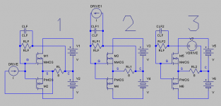
Actually, the way this output stage is driven, it works more like a source follower than a common-source amplifier. See the attached picture. 1 and 2 are essentially equivalent because the drive current is very small and output impedance is very low - especially after global feedback is applied. 2 and 3 are exactly equivalent, it's just a Norton source changed to its Thevenin equivalent. The stage has just as much local feedback as the standard follower.
It depends on what you are measuring of course. 🙂 If talking about output impedance then there is no load by definition. What is measured is the impedance as seen from where a load would be. You can measure in the other direction too, in that case the amplifier isn't there. It's what the amplifier sees that is measured.
Finally, you can measure impedance as seen by something else which is also about to be connected to the loaded output like you suggest. It can be a very useful measurment to do for understanding how external disturbances might affect operation.
Anyways, supply fluctuations, just like in a source follower, see a very high impedance, causing only small current variations. There is also as much local feedback in the output stage as in a source follower circuit, attenuating them even more. Then there's global feedback around that, attenuating it again.
darian said:Right Megajocke, the output is a current source, but the imperfect PSU in serie with the load modulates the collector to drain voltage of the output transistor and then in return modulates the transfer function too.
You can't escape this bad bad effect of the PSU in serie with the load.
I agree all this must be very minimal, but still it does count. After all, It is hard to think about something less linear and more frequency dependant than a standard PSU!
Actually, the way this output stage is driven, it works more like a source follower than a common-source amplifier. See the attached picture. 1 and 2 are essentially equivalent because the drive current is very small and output impedance is very low - especially after global feedback is applied. 2 and 3 are exactly equivalent, it's just a Norton source changed to its Thevenin equivalent. The stage has just as much local feedback as the standard follower.
And finally, technically speaking, when a load is connected to the output, it is in parallel with the high output impedance of the "current source", so the output impedance is the impedance of the load itself. So the output impedance becomes not that high. At least it's how I see it.
Regards
It depends on what you are measuring of course. 🙂 If talking about output impedance then there is no load by definition. What is measured is the impedance as seen from where a load would be. You can measure in the other direction too, in that case the amplifier isn't there. It's what the amplifier sees that is measured.
Finally, you can measure impedance as seen by something else which is also about to be connected to the loaded output like you suggest. It can be a very useful measurment to do for understanding how external disturbances might affect operation.
Anyways, supply fluctuations, just like in a source follower, see a very high impedance, causing only small current variations. There is also as much local feedback in the output stage as in a source follower circuit, attenuating them even more. Then there's global feedback around that, attenuating it again.
Hi All
I would like to thank everyone for their inputs and tolerance. I think I have the Power Supply figured out. If I am wrong, please let me know.
The 2 Supply rails glide up or down in tandem when there is a difference in current between them. This "floating" PS is possible because the mid-point is not referenced to Ground.
Can anyone explain the benefits of having such a PS arrangement. Reason being that we now need 2 transformers, one for each channel, or a single transformer with 2 identical secondary windings.
Cheers
Mike
* The front end of the amp doesn't need high voltage supplies - the output stage only needs +-10V or so on the gates for full output. The drivers can be run at high idle current without high power dissipation in them. Look at those transistor numbers, they are in small TO-92 cases all of them!
* These mosfets have the source connected to case - and with this configuration all FET:s can be mounted on the same, and non-live, heatsink without insulating washers for better thermal transfer. The QSC circuit using bipolars has this advantage too. (collectors grounded but they are CFP) It is possible to do the same thing with live heatsinks at rail voltage (or output node in the case of lateral fets) but you have to be careful when you have large pieces of metal with voltage between them of almost 200V DC...
* These mosfets have the source connected to case - and with this configuration all FET:s can be mounted on the same, and non-live, heatsink without insulating washers for better thermal transfer. The QSC circuit using bipolars has this advantage too. (collectors grounded but they are CFP) It is possible to do the same thing with live heatsinks at rail voltage (or output node in the case of lateral fets) but you have to be careful when you have large pieces of metal with voltage between them of almost 200V DC...
Hi megajocke
Thank you for your thoughts.
I do fully agree with you on the voltage amp and grounded source for the power mosfets.
Having read through Mr Strickland's patent again, I think there are more reasons for implementing such a "Sliding Power Supply". This amplifier can still work with fixed rails after all.
I believe this "Sliding Power Supply" is to enhance the efficiency of the power stage. According to Hafler's specs, the P9505 is rated for 250W/ch into 8 ohms. I assume the P9500, which is the schematic we are looking at, is of the same or similar power rating.
With a conventional PSU, for 250W output, we are looking at rails of about +/- 75V. Its not very clear in the schematic but it looks like the Hafler's rails are at +/-35V. Because of its unique properties, the rails can slide up another 35V and down another 35V, effectively giving a +/- 70V rails. It is similar to rails switching (Class H?) but due to its seamless nature, there are no switching artifacts.
With the ability to run a 250W/8 ohms power amp with only +/-35V, they now have the luxury of biasing the lateral mosfets higher. In the P9505, the amp is specified as drawing 2A current when idling. Assuming there are a total of 8 power mosfets, this works out to 250mA each. This is much more manageable when compared to 250mA each with +/- 70V rails. More wasted power and a lot more heatsinks. The only disadvantage I can see is this type of "Sliding Power Supply" necessitates the PS cap to be in series with the load. Apart from that and of course, a dedicated set of transformer secondary windings, it actually is quite appealing. I find it odd that only a few manufacturers, QSC is the most obvious, embrace such a PS concept.
Since we are on the topic of Mr Strickland's patents, would you be kind enough to assist me. There are supposed to be 3 Feedback loops. I can only find the Global NFB and Local FB for the Power stage. Where is the Positive Feedback?
Thank you for your time.
Cheers
Mike
An externally hosted image should be here but it was not working when we last tested it.
The 9505 schematic can be found here: http://www.audio-circuit.dk/images/schematics/Hafler-9505-pwr-sch.pdf
The rails are about +/- 88VDC.
Cheers,
Paul
The rails are about +/- 88VDC.
Cheers,
Paul
Hi Paul
Thanks for pointing that out. So, its working at the same rail voltages as a conventional PS. There goes my theory of "Sliding Rails".
Looking at it again, it behaves like a conventional PS. The rails sag slightly when current is drawn. Only difference is instead of coming out of the source end, it is at the mid-point of the PS caps.
Since it doesn't improve the PS efficiency, what are the advantages of doing it this way. We have a situation where the PS caps are in series with the load and like you said earlier, it doesn't block DC if any mosfets fail? Would it not be better to revert back to the convention PS and have the output from the source and ref the 0V back to the PS.
Cheers
Mike
- Status
- Not open for further replies.
- Home
- Amplifiers
- Solid State
- Could someone explain this Hafler/Strickland output topology to me?