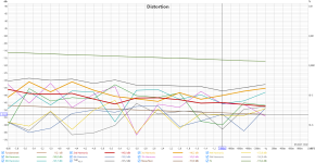
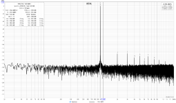
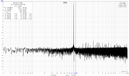
9039Q2M is a phenomenal DAC with 1k@THD about -150db(at 24MHz MCLK + very little individual THD compensation), however, if you measure each out+ and out- separately, you'll see not so wonderful THD performance but exactly the same harmonic to harmonic symmetry of the distortions. I think that such a crazy symmetry is the main feature of 9039Q2M. A differential opamp stage with all 4 resistors equal has different input currents for a balanced input signal, and ruining the symmetry, hence, increasing the final THD. For instance, AP SYS2522 sine gen being balanced, has no such problem but 9039S has, that's why there are 510/510 and 180/180.
But if your LPF is used with the 9039S dongle, then it should not be a problem because the 9039D has an output buffer?
9039S, yes 360ohms is literally nothing for that DAC, even 12ohm load THD+N<-120db. Any balanced output will work fine(because being loaded equally neg and positive) if not too high Zout.
But nice to reflect on that 0.2% of 360ohm is 0.720R
So to match resistor tolerance in unbal stage, it is not room for much output Z variation on source.
So to match resistor tolerance in unbal stage, it is not room for much output Z variation on source.
But I really like to have access to such a low noise unbalancer.
But it was a little more demanding to the source than I anticipated.
But it was a little more demanding to the source than I anticipated.
not only the noise is low but THD and Zout 100mOhm with 100mA. You can turn a high-quality balanced DAC(unbalanced outputs are usually a lot worse) output into an unbalanced output with the ability to drive headphones keeping max possible performance(opa1612/opa1656 composite with Aol 170db@1k).But I really like to have access to such a low noise unbalancer.
The input caps beeing the weak point regarding distortionin in low bass.
But only academic interest. No practical implication.
(Alu cap in front of low Z combined with high voltage and low frequency)
But only academic interest. No practical implication.
(Alu cap in front of low Z combined with high voltage and low frequency)
But interesting to use a SMSL SU-9 Pro XLR and ADCiso
Same output
ADC values.
0 dBr in sw9 and sw10 open, 100mV rms
-5,74dBr in sw10 open, 51,51mV rms
-11,90dBr in sw9 open, 25,44mV rms
Same output
ADC values.
0 dBr in sw9 and sw10 open, 100mV rms
-5,74dBr in sw10 open, 51,51mV rms
-11,90dBr in sw9 open, 25,44mV rms
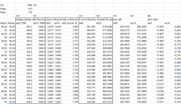
Since the resistance of the legs are different but precission, I wonder if the Unbal circuit can be used to measure the source resistance


I am optimistic, but a lot of variables so plenty room for error.
1 volt in with no source gives 2 volts out
Opening and closing sw 9 and 10 measure gains.
And then scaling to new 2 volts out vith Rs and find possible values.


I am optimistic, but a lot of variables so plenty room for error.
1 volt in with no source gives 2 volts out
Opening and closing sw 9 and 10 measure gains.
And then scaling to new 2 volts out vith Rs and find possible values.
This is LTspice file and the Google sheet.
Problem solver in Google sheet can not solve with two inputs so I had to search for the right values myself.
Start with ballgame numbers and iterate.
The total source resistance is split two values so two values needed as input.
There are three gains that are changing by changing the two source resistances.
- Gain with sw 9 and 10 open
- Gain with sw 9 open
- Gain with sw 8 open
- Find value for sw 9 and 10 open
- Find value for sw 9 open. The vaulue for 'dB in ADC sw 9' is the difference to 1.
- Find value for sw 10 open. The vaulue for 'dB in ADC sw 9' is the difference to 1.
- Search for the values in 2. and 3 by changing Rspos and Rsneg. When the values are found. That is the Rsourse resistances.
Attachments
Now that's a chip! What is the difference between cascadeing and paralleling the channels. I have read about paralleling, it raises the SNR and THD. What advantage does cascading offer?
There is another way to use two ADCs, which is to extend dynamic range beyond that of one ADC chip. The use of that technique has become increasingly common.
Take a look at the datasheet. Cascading is hooking up the channels in series. Paralleling is hooking them in parallel. I agree, the paralleling reduces noise. I guess cascading must increase dynamic range.
Ohh, I know what you're talking about, but I'm not a flaming enthusiast of such tricks - it is useless for audio measurements and semi-useless for musicians too.
I just replied about it in another forum:
"Well, the paralleling is fine(BTW, 9822 it seems also has some I2S features for that) but cascading, idunno. IMO, it is a 99.99% marketing feature for musicians or others who can't realize that such DR isfake arguable. It's similar to a DSD feature of 9822, it is there but.. made from PCM and what? So, I think we need to test the linearity of 9823 first(especially at 10kHz, after I took a look ESS recommended frontend). I noticed that TD+N specs were done at -1dbfs, and I worry a little. THD+N of a calibrated MONO 9823 is expected to be around 3db better than APx555, how many DIYers want even better and are ready to pay for that?"
I just replied about it in another forum:
"Well, the paralleling is fine(BTW, 9822 it seems also has some I2S features for that) but cascading, idunno. IMO, it is a 99.99% marketing feature for musicians or others who can't realize that such DR is
- Home
- Vendor's Bazaar
- Cosmos APU a notch+LNA $70 to outperform APx555b for $30,000


