Inspired by Siegfried Linkwitz and Rudolf Finke i started a new speaker-project - a 4 way speaker, full range dipol, working title: cosinus
Why dipole? Because of the acoustic energy radiated in to the room - to see and show the differences i did some simulation using "Boxsim".
Attachment 1:
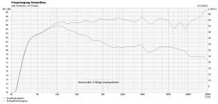
shows the level on axis (upper line) and the energy that is radiated into the room for a well buildt classical 3way Bassreflex speaker
Attachment 2:
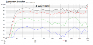
shows the level on axis (upper line) and the energy that is radiated into the room for a 4way dipole speaker, similar to the one Siegfried Linkwitz has buildt
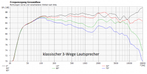
The line for the energy describes the sum of the acoustic energy under angle radiated in to the room - and is therefore a good description of how the speaker sounds. To make it a little clearer, let us have a closer look to the angles 30, 60 and 75degrees. Just looking at the radiation to the listeners direction they ideally should be down in level as the function the cosinus, so 30° should read about -1.3dB, 60° should read -6dB and 75° should read -12dB. The following Attachments show that the dipol speaker comes a lot closer to that ideal radiation under angle than the classical speaker construction.
Attachment 3:
classical 3-way speaker
Attachment 4:
4 way dipole speaker
Why dipole? Because of the acoustic energy radiated in to the room - to see and show the differences i did some simulation using "Boxsim".
Attachment 1:
shows the level on axis (upper line) and the energy that is radiated into the room for a well buildt classical 3way Bassreflex speaker
Attachment 2:
shows the level on axis (upper line) and the energy that is radiated into the room for a 4way dipole speaker, similar to the one Siegfried Linkwitz has buildt
The line for the energy describes the sum of the acoustic energy under angle radiated in to the room - and is therefore a good description of how the speaker sounds. To make it a little clearer, let us have a closer look to the angles 30, 60 and 75degrees. Just looking at the radiation to the listeners direction they ideally should be down in level as the function the cosinus, so 30° should read about -1.3dB, 60° should read -6dB and 75° should read -12dB. The following Attachments show that the dipol speaker comes a lot closer to that ideal radiation under angle than the classical speaker construction.
Attachment 3:
classical 3-way speaker
Attachment 4:
4 way dipole speaker
Attachments

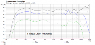
The energy radiated to the speakers back is what is needed to create a wide illusion of 3 dimensional space, to locate the actors and the instruments and to give the listener an almost holographic picture. This works very well when the sound radiated to the back is about 15dB down in level and at least 6ms delayed. Therefore it is best to have at least 1m distance to the rear wall. The dipole speaker brings no energy into the room under the angle of 90° (cos 90° = 0), so there are no loud early reflections to disturb the illusion.
The classical speaker does not very well at this point as can be seen in the simulations to the speakers back:
Attachment 1:
classical speaker
Attachment 2:
dipole speaker
(both speakers are the same as in the last post)
next post will be a first description of my dipole
The classical speaker does not very well at this point as can be seen in the simulations to the speakers back:
Attachment 1:
classical speaker
Attachment 2:
dipole speaker
(both speakers are the same as in the last post)
next post will be a first description of my dipole
Attachments

The first thing that comes to the eye is the low level at the lower end of the scale. Therefore the practical dipole is different here - at this end of the spectrum i use a "Ripol". This is a patented form of a folded dipol, invented by Axel Ridthaler. The "Ripol" promises level down to 30Hz without equalizing (or 25Hz with moderate equalizing). This kind of dipole is similar to the W-Frame dipole of Siegfried Linkwitz (that he used in his Orion-speaker as far as i remember), but with a much smaller enclosure, in a way that the air enclosed is an extra load for the speaker used here. The effect is a lower resonance frequency of the speaker when mounted. A negative side-effect of this kind of mounting is the limited frequency range that can be used as about 300Hz there is a massive resonance of the enclosure . So i use the "Ripol" to the maximum frequency of 185Hz, cut by a 24dB Linkwitz-Riley low pass.
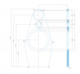
To get the radiation of the dipole as posted in post 1 it is neccessary that the baffle is as small as possible and to limit the speaker to his natural upper end (where it starts to radiate only to the front). So it came to a 4-way speaker.
Another problem is the tweeter, only radiating in one direction. Another one mounted back to back is part of the solution. But when mounted this way, the baffle that results is much wider than the active part of the tweeter. So it is neccessary to put the crossover frequency relatively high - so that the tweeter can not see the baffles edges.
And as form follows function, the shape af the baffle that results could look like the one attached.
Attachments
When building a speaker it is always a good thing to have reliable data on the speaker-chassis you want to pick. My source of reliable data is the Magazine "Hobby HiFi" by Bernd Timmermanns. This helped me to pick the chassis i use in the cosinus dipole.
The tweeter:
omnes audio T25H, a 25mm neodymium tweeter with excellent data that costs almost nothing (15€)
The upper mids:
Visaton B80, a 80mm full range speaker, motorised also by neodymium and therefore able to radiate well to the backside (69€)
Also possible at this position is the 80mm fullrange speaker by omnes audio, which is almost identical to the Visaton B80 - but a little lower in price (about 40€, as i remember)
The lower mids:
Visaton BG20, a 185mm full range speaker, intentionally made by Visaton for musicians, that behaves very well at the range (30€)
The sub:
Peerless SLS12, a 280mm woofer with a low resonance frequency, sold by Axel Ridthaler for his "Ripol"- enclosure in combination with the confidential construction plan for a price that is moderate higher than the chassis itself.
Common for all the chassis is that they are free of unpleasant resonances (at least in the range they should work) and they all have low THD at 90dB SPL (well below 1%)
[note that the diameter described at the chassis above is the one of the moving part]
I am not sure if you have finalized your design. If not yet, then would like to make a suggestion. It would be better to use a dipole tweeter, and to mount that on top (above) the baffle instead of within the baffle. The crossover point to the midrange will need to be approximately 2k Hz. It's best to stay dipole up to at least 5kHz-7kHz, but that is in my opinion too high for a mid-to-tweeter crossover point (yes, I know that the LX521 has it).
I agree with Charlie!
How about making a simple test baffle first, to test and measure radiation patterns of different layouts?
Rearside or dipole tweeter adds naturalness to sound, recommended!
How about making a simple test baffle first, to test and measure radiation patterns of different layouts?
Rearside or dipole tweeter adds naturalness to sound, recommended!
Also, because of dipole losses I am concerned that the woofer will be challenged to make it down to 185Hz where you can cross over to your Ripole. Can you use a 300mm unit instead?
Very cool project! Do you already have the drivers?
I´m using the SLS12 on a slim OB-baffle (together with a horn/HF108 ATM) up to 1.1kHz and it does have quite a nice midrange for such a big woofer.
This is admittedly not a good dipole speaker but what I want to say is, you could easily skip the BG20 and put that SLS12 on the baffle.
You could meet the B80 at 300Hz+ maybe and have both sweet midrange and good bass.
The 830669 has a very nice bass even on that slim baffle and with some EQ and wings (U-frame), a sub might not be needed.
That said I often thought about using those 2xSLS12 in a ripole myself.
There exist free plans on the net if you search for them.
Here´s another cheap alternative if you should want to put the SLS12 on the baffle and still use ripoles:
Killer dipole bass dirt cheap
Last edited:
BTW: does anyone know what happened to Rudolf?
Still enjoy reading his old posts, he was such knowledgeable guy when it comes to speakers and especially OB. Met him once at a DIY exhibition. The same nice guy that he is online too.
Still enjoy reading his old posts, he was such knowledgeable guy when it comes to speakers and especially OB. Met him once at a DIY exhibition. The same nice guy that he is online too.
Last edited:
The design is finalized and to use the tweeter on top is definitely no good idea - i have tried this with an earlier testbaffle and could not find a crossover that worked. Therefore my words above: the tweeter should not "see" the baffle. The configuration stays dipole well above 7kHz. The lower mids (i think this is what you called the woofer, Charlie) works very well at 185Hz. Could probably a challenge when the listening level is very high as the linear Xmax is only +/-2mm.
A dipole tweeter is for sure a good idea as you only need one and you have no delay between the front and the back in that range, but there are very few on the market - and the few i know do not measure very well, especially when used with low levels.
As the design is finalized i do already own the drivers. Taking the SLS12 for the lower mids would probably work - but the design that results would not please my eyes.
My cosinus - dipole is an active setup, actually buildt with a minidsp 4x10HD and a dayton audio MA1260 - the MA1260 is ok for the money and doesen't "hurt", but it is definitely at the lower end of HiFi and needs to be replaced (that is the next project!)
When the speakers got mounted i did a quick on axis mesurement for the two mids and the highs and compared it with the simulation data i showed above. The simulation was very close to reality, there were very few changes to be made. I expected that, as the simulation could not reproduce the exact shape of the baffle. A complete verification measurement needs to be done - but this has to wait until i find a location to do this and my own amps are buildt.
How does it sound?
As described above, three dimensional, almost holographic, rich on detail. You instantly hear if the recording is well done. The weakest part of the HiFi chain is no longer the speaker, now it is the recording.
In my experience this has never been true for a midrange driver. Can you please show measurements on and off axis, or at least to the rear on axis, that demonstrate that the speaker is a dipole to 7kHz? Because if it IS a dipole to 7kHz (where you cross over to the tweeter a la SL I think) then I would very much like to know more about the midrange you are using!The configuration stays dipole well above 7kHz.
Let me explain a little more about my comment. Sure, the driver can be made to operate to 185Hz by applying more power to lower frequencies. But the baffle and driver are not all that large, so I am concerned there will be too much baffle loss. This might mean that you have to apply a lot of power, then you could get power compression from heating of the voice coil or push excursion to Xmax. I find that distortion is magnified for this driver because of the dipole losses. Have you measured distortion on the driver with the frequency response corrected to be flat? A larger driver has an easier job and that is why I made the suggestion.The lower mids (i think this is what you called the woofer, Charlie) works very well at 185Hz. Could probably a challenge when the listening level is very high as the linear Xmax is only +/-2mm.
A dipole tweeter is for sure a good idea as you only need one and you have no delay between the front and the back in that range, but there are very few on the market - and the few i know do not measure very well, especially when used with low levels.
As the design is finalized i do already own the drivers. Taking the SLS12 for the lower mids would probably work - but the design that results would not please my eyes.
My cosinus - dipole is an active setup, actually buildt with a minidsp 4x10HD and a dayton audio MA1260 - the MA1260 is ok for the money and doesen't "hurt", but it is definitely at the lower end of HiFi and needs to be replaced (that is the next project!)
When the speakers got mounted i did a quick on axis mesurement for the two mids and the highs and compared it with the simulation data i showed above. The simulation was very close to reality, there were very few changes to be made. I expected that, as the simulation could not reproduce the exact shape of the baffle. A complete verification measurement needs to be done - but this has to wait until i find a location to do this and my own amps are buildt.
How does it sound?
As described above, three dimensional, almost holographic, rich on detail. You instantly hear if the recording is well done. The weakest part of the HiFi chain is no longer the speaker, now it is the recording.
Just one more question in case I am confused: Is it correct that there is one tweeter? And you are crossing to it from the midrange at 7kHz?
Also, when I mentioned "tweeter on top" I meant not in the baffle at all but on top of it. If you put a dipole tweeter in the baffle that will definitely make a mess out of the response.
Anyway, it seems everything is finalized at this point. Please make many, many measurements so we can "see" how the speaker operates (since we cannot hear it). This can include the frequency response on axis at front and rear, and off axis at least at 20-40-60 degrees. A distortion measurement or two at e.g. 90dB@1m or 96dB@1m performed in front of the speaker is also useful information.
Last edited:
on the backside of the speaker i expect for sure to see some imperfections because of the speakers magnets, especially in crossover region from the upper mids to the highs, and for sure i will show some measurements - but this needs time. I am looking for a location where i can mesure down to at least 100Hz without reflections. I do not want to use nearfield measurements.
The actual crossover to the highs is 5.5kHz and of course there is a second tweeter to the rear. The shape of my testbaffle around the tweeter was not wider than the tweeter itself. When you want to use the tweeter that way the crossover has to be in the range well above 10kHz and you get a problem with the dipole behaviour of the upper mids. And surely - the lower end of the lower mids will be the weakest part of this construction.
The actual crossover to the highs is 5.5kHz and of course there is a second tweeter to the rear. The shape of my testbaffle around the tweeter was not wider than the tweeter itself. When you want to use the tweeter that way the crossover has to be in the range well above 10kHz and you get a problem with the dipole behaviour of the upper mids. And surely - the lower end of the lower mids will be the weakest part of this construction.
Upper mid and tweeter can be measured indoors quite well, set distance to 0,5 - 1m, speaker in the middle of the room, mic diagonally. 5-7ms gating can be used, check the timing of first reflection! Use a turntable for horizontal off-axis. Vertical off-axis is more difficult, but handheld tilting can give a rather good estimate for you. Better than waiting for next summer...
Me neither didn't understand that you have the speaker(s) ready already, sorry. By the way I got invaluable help from Finke by email in 2013. His website is still running Dipolplus - Alles über offene Schallwände Summary in English is available as pdf
Me neither didn't understand that you have the speaker(s) ready already, sorry. By the way I got invaluable help from Finke by email in 2013. His website is still running Dipolplus - Alles über offene Schallwände Summary in English is available as pdf
Last edited:
Interesting project! Hope you get the bass right, so it achieve the same warmth effect as with regular speakers.
And one more thing, isn't the dipole effect already recorded? Most recorded sound sources are omnical before entering the mic so now it will be a dual omnical effect? ... Or the dipole will transform the sound source back to its original state? Just speculating 😎
And one more thing, isn't the dipole effect already recorded? Most recorded sound sources are omnical before entering the mic so now it will be a dual omnical effect? ... Or the dipole will transform the sound source back to its original state? Just speculating 😎
Interesting project! Hope you get the bass right, so it achieve the same warmth effect as with regular speakers.
And one more thing, isn't the dipole effect already recorded? Most recorded sound sources are omnical before entering the mic so now it will be a dual omnical effect? ... Or the dipole will transform the sound source back to its original state? Just speculating 😎
No, your thinking is totally wrong. Microphone techniques and mixing are another saga, and some sounds are totally synthetic. "Recordings" are mixed and mastered in studios with normal loudspeakers and headphones.
When we replay recordings with loudspeakers, their radiation pattern will determine how that sound gets dispersed and reflected from boundaries in the room. Dipole speakers have own identifiable sound, they fill the room with sound but still give good stereo image (if they are installed right). This suits best for classical music, but it is also a question of personal preference. Another very specific sound comes from large horns.
Yes, i can measure the mids and the highs in a small room, that is what i did when doing my quick on axis test - but i want to test the complete speaker down to at least 100Hz, and this not possible in a small room.
"Dipolpus - alles über offene Schallwände" downloaded as .pdf is the document that helped me a lot when thinking about how to design the baffle. So did the homepage of Siegfried Linkwitz....
"Dipolpus - alles über offene Schallwände" downloaded as .pdf is the document that helped me a lot when thinking about how to design the baffle. So did the homepage of Siegfried Linkwitz....
I read some pages of your link to the "AINOgradient speaker project" Juhazi, and there is just one thing to comment: well done!
The kind of perfection you show there was never intended by me when building my "cosinus dipole", the perfection to the rear side is only of academic interest for me, as this part is delayed, reflected and down in level anyway....
A perfect dipole at high frequencies is also impossible due to the physical size of the high range driver....
But that is what speaker building is: find a good compromise that will work for you.
My intention to show my construction here is to make dipole speakers more popular as there are closer to the "musical reality" than other kinds of speakers (at least to me and my wife (who is an active musician herself) and some friends who call high priced HiFi-equipment their own)
The total sound power coming from the room might only be 6 dB below the on axis sound pressure in a small room. I would not discount it. I can listen to the room sound all day long by sitting in the null of a dipole speaker. It is important that the reflected sound is as similar in tonal balance as the direct sound.to the rear side is only of academic interest for me, as this part is delayed, reflected and down in level anyway....
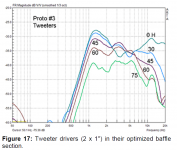
This is not correct in my experience. There are several tweeters e.g. AMT types that have a dipole pattern over their entire frequency range. Take a look at the data (sorry that it is somewhat limited) in this thread for example, especially post #13:A perfect dipole at high frequencies is also impossible due to the physical size of the high range driver....
measurements of nude ribbons and a dome-dipole
This is why I suggested that you use one in your system (but at the time I thought you were using a front tweeter only). Also, I could argue that no loudspeaker is a "perfect" dipole at any frequency except very low ones.
If you can get your 2 tweeter setup to look like the data in this post I will be impressed:
measurements of nude ribbons and a dome-dipole
But it will probably look more like the attached picture (this is the response of SL's LX521 tweeters). You can see why he has to cross over at 7kHz. Between 2k Hz and 6kHz the pattern is bad.
Attachments
Last edited:
It took a while to build the amps for the speaker. As their build is done the time has come to measure the speaker completely. I know how to measure the mids and the highs in a small room, but i am not sure if i am right in the way i measure the frequencies below. Referring to D' Appolitis book about how to measure speakers i want to do it the following way:
1.) measuring the frequencies above 500Hz in a distance of 1m and gated, to get the data of the speaker itself
2.) measuring the frequencies below 500Hz in a distance of 2m in a real big room (or outdoor) and no objects close to the speaker to be measured, using ground-plane measurement (with the idea in mind that i do not have to adjust level for the measurement). Do i get the correct level when doing the measurement that way?
- Home
- Loudspeakers
- Multi-Way
- cosinus - a 4way dipole speaker