It looks like the LED backlight supply is connected to the two lefthand pads of that group of four. Beware of polarity and voltage.
Next pad appears to be audio ground (speaker -) and the right hand pad goes to speaker +
Next pad appears to be audio ground (speaker -) and the right hand pad goes to speaker +
I'm not familiar with these. There is PCB with them, not naked instrument. In the central part there are two LED light connectors and two connectors for the VU instrument. You should draw a schematic of that PCB with all the elements in order to figure out what to do. Try to ask for the schematic from the seller with the parameters of the instrument.
I got this back from the Seller. So I guess I should solder the led legs and the gauge tags that are poking through.
Does anyone have a schematic of how I wire this with a Stereo Log Volume Pot?
Does anyone have a schematic of how I wire this with a Stereo Log Volume Pot?
Attachments
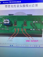

Yes all of them should be soldered on PCBs. The trimmer on the PCB potentiometer adjusts the VU meter display.
This VU meter should be connected to the output of the amplifier, not to the potentiometer.
This VU meter should be connected to the output of the amplifier, not to the potentiometer.
looks good. gonna give it a try. pozdrav
- Status
- Not open for further replies.