If the strobe pattern appears stationary, is that it? That means the speed is good enough? How meaningful is this method?
Hey, Guys - I may be way off base here but I was always convinced that the strobe light had to be LOCKED to the motor - i.e. if the motor is AC then the neon strobe is locked to it through sharing the 60Hz from the mains.
My Ariston (dc belt drive) and my Pioneer PL51 (direct drive) both take their strobe light source from the motor controller.
May be just my tired old brain
 but I can't see how the strobe light would have any relation to the pattern on the platter unless they shared the same timebase.
Jess
No, doesn't need to be locked. Many TTs use the neon bulb method, because it's a cheap way to get a light flashing at 50/60 Hz. Any light that flashes at the right rate will work. The more precise it is, the better for checking speed.
However, while the line frequency has good long term accuracy, it varies markedly in the short term.
However, while the line frequency has good long term accuracy, it varies markedly in the short term.
pixpop-
I built the strobe from Vinyl Engine , it is virtualy identical to the circuit described by dice45 in this thread , and has a duty cycle around 5%. I find it provides a clear/clean pattern.
Basically..yea. The question is, how still is it? Without a stationary sight/line to compare to, it's next to impossible to see a slow drift. Additionally, you are looking at a "no load" condition..what does it do during a prolonged heavy passage? I remember seeing a formula somewhere that you could use to calculate speed based on long term drift down to a tiny fraction of a percent.
Thanx, I'll check em out.
Jess-
Check out the posts by dice45 I linked above for an excellent explanation of all things strobe..it's my reference .
-Casey
Edit:Fixed URL on link.
It helps to drive the LED(s) with an extreme duty cycle and lots of current. A short, very intense pulse. I built mine this way. It flashes at 120 Hz, with about a 1% duty cycle.
I built the strobe from Vinyl Engine , it is virtualy identical to the circuit described by dice45 in this thread , and has a duty cycle around 5%. I find it provides a clear/clean pattern.
If the strobe pattern appears stationary, is that it?
Basically..yea. The question is, how still is it? Without a stationary sight/line to compare to, it's next to impossible to see a slow drift. Additionally, you are looking at a "no load" condition..what does it do during a prolonged heavy passage? I remember seeing a formula somewhere that you could use to calculate speed based on long term drift down to a tiny fraction of a percent.
Oh, Parts Express has UV LEDs
Thanx, I'll check em out.
May be just my tired old brain but I can't see how the strobe light would have any relation to the pattern on the platter unless they shared the same timebase.
Jess-
Check out the posts by dice45 I linked above for an excellent explanation of all things strobe..it's my reference .
-Casey
Edit:Fixed URL on link.
Dab-Nabit 😡
I looked up the PE UV LED and it peaks at 390 nm.
From the ClearNeon site...
I'm sure this LED has some output below 380 nm, but I'm hoping to find one closer to the "magic" 365 nm.
Anybody got another source?..anyone?..anyone?..Beullar?
-Casey
I looked up the PE UV LED and it peaks at 390 nm.
From the ClearNeon site...
UV A : 340 - 380nm Proper wavelenght to excite ClearNeon Blacklite...For best results With ClearNeon we want our peak transmission of UV A to be around 365nm (longwave UV) this is the Magic frequency for exciting and illuminating our paint.
I'm sure this LED has some output below 380 nm, but I'm hoping to find one closer to the "magic" 365 nm.
Anybody got another source?..anyone?..anyone?..Beullar?
-Casey
pixpop said:No, doesn't need to be locked. Many TTs use the neon bulb method, because it's a cheap way to get a light flashing at 50/60 Hz. Any light that flashes at the right rate will work. The more precise it is, the better for checking speed.
That's right. As has previously been said, you want a harsh duty cycle and plenty of current, but the actual frequency can be varied to suit the strobe disc. If I was in the situation of making a strobe disc, I'd work out what was the easiest strobe disc to make, then calculate the frequency required from the strobe light and see if it was feasible (crystals are mostly available in standard frequencies).
The Technics SP10mkII feeds the strobe light from the motor control, so all it shows is that the servo is working - it doesn't show if the platter is rotating at the right speed. You want an independent oscillator for the strobe light, then if it agrees with the platter, chances are the platter is rotating correctly.
Not the cheapest way to get them, UV LED Flashlight - 2 LEDs
Wavelength: 365 or 375 nm +/-5 nm
Maybe you can ask for samples?
HIGH FLUX UV LED ILLUMINATORS OTLH-0480-UV
or
the fox group inc
Regards
James
Wavelength: 365 or 375 nm +/-5 nm
Maybe you can ask for samples?
HIGH FLUX UV LED ILLUMINATORS OTLH-0480-UV
or
the fox group inc
Regards
James
Hi tvi-
The flashlight might be my fall back option, yea it's pricey for 2 LED's, but it might not be to pricey compared to a bulk order. The array is just to much light. Thanx for the links.
I have discovered why finding UV LED's is such a problem..LAWYERS. Evidently they have decided that just because someone has the skill to use them, doesn't mean they aren't dumb as a rock, and might try looking directly into them. Why the same concern doesn't apply to the laser LED's you can buy at the mini-mart is beyond me. I discovered this after I found what appears to be the ideal specimen, the Nichia Corp.'s NSHU590B, a UV LED with a peak at 365 nm +/- 5 nm. So far so good..one little inconvenience though..I had to fax them a signed waiver (copy attached) that simply states I know I can hurt myself if used improperly. A CYA doc for the files.
So now I wait for confirmation to see if I will be honored, and allowed to purchase from them..sheesh.
Still looking for the best UV blocking option.
-Casey
Attachments
Might it be an idea to scavenge the edge of an el cheapo turntable with already the marks on it. its the kind of manufacturing that would be very annoying if you do not get it exactly right.
neutron7-
That is an excellent idea, and if the strobe was the only goal I would take you up on it (I still might). You see, everytime I take on a difficult task, I end up with a capability in my shop that I didn't have before. I have wanted to accuratley divide a circle for a very long time (laying out divisions by hand is a major PITA), and getting a circle a foot in diameter divided evenly and accurately within a few thousandths of an inch is an opportunity to fine tune the gear, and skill required.
In short, it's an opportunity to improve.
On another note, I think I found my UV Blocker. However I do it (cut my own, or scab on a pattrn from a donor), my strobe will be pretty cool.
-Casey
Might it be an idea to scavenge the edge of an el cheapo turntable with already the marks on it. its the kind of manufacturing that would be very annoying if you do not get it exactly right.
That is an excellent idea, and if the strobe was the only goal I would take you up on it (I still might). You see, everytime I take on a difficult task, I end up with a capability in my shop that I didn't have before. I have wanted to accuratley divide a circle for a very long time (laying out divisions by hand is a major PITA), and getting a circle a foot in diameter divided evenly and accurately within a few thousandths of an inch is an opportunity to fine tune the gear, and skill required.
In short, it's an opportunity to improve.
On another note, I think I found my UV Blocker. However I do it (cut my own, or scab on a pattrn from a donor), my strobe will be pretty cool.
-Casey
Well, I was able to navigate through Nichia Corp.'s maze, and my UV LED's are in route. It wasn't difficult really, just silly. I received an e-mail confirming that my signed waiver made it to there office, and was told that they had to know what I was going to use them for before they could authorize the sale.Umm..OK, so I e-mailed back and told them. I then got word back that my account was now authorized to purchase them, but that I needed to be aware that they were classified 1M under the IEC 60825 code which they attached to the message. Not knowing the IEC code from Adam, I was starting to wonder if this device was actually hazardous as I looked it up. Good grief..
“1M- Considered as safe to eye and skin under all reasonable foreseeable conditions of operations, provided they are not viewed with magnifying optics of any kind”

After all that, they were quite reasonably priced at $5.60 ea., so I ordered 2.
-Casey
“1M- Considered as safe to eye and skin under all reasonable foreseeable conditions of operations, provided they are not viewed with magnifying optics of any kind”
After all that, they were quite reasonably priced at $5.60 ea., so I ordered 2.
-Casey
you should try buying the extra powerful epoxy 805? from 3M 🙂 the thing you have to sign is like war and peace.
how powerful are the LEDS? I need some strong UV ones.
how powerful are the LEDS? I need some strong UV ones.
how powerful are the LEDS? I need some strong UV ones.
The Nichia's I ordered are a whopping 1.4 mW optical output..if your looking for a sunburn, I would checkout the T-66 mounted array that tvi linked to earlier.
-Casey
This turned out to be one of those weekends where I didn't get near as far as I had hoped..everything seemed to fight me. I didn't get the table spinning again, but some progress was made.
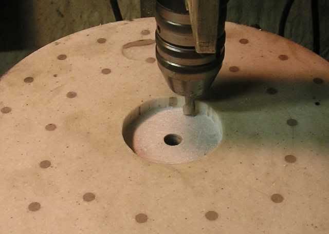
First up was re-cutting the recess for the spindle bearing. The gap between plinth and platter was .1” , and I wanted .03”, so I cut it down .07”...
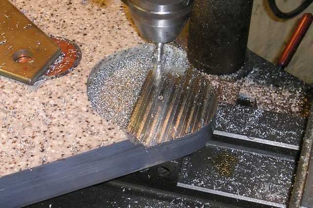
I remounted the bearing and platter to measure how deep I needed to cut the motor cutout, and proceeded to mill out .34” This about half way though...
And here it is finished...
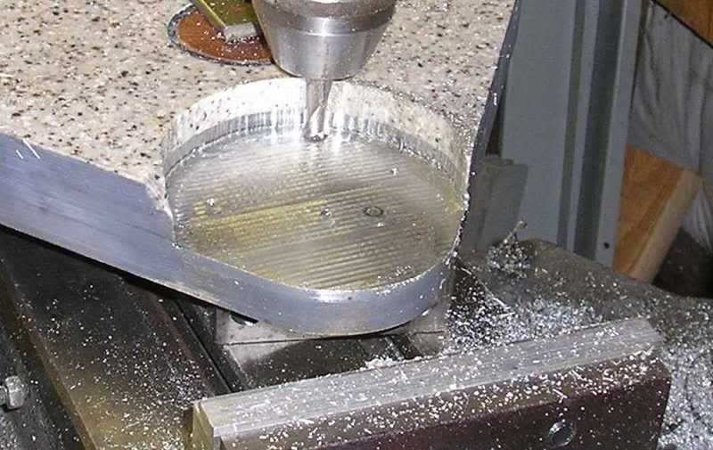
This was a time consuming PITA. Not wanting to de-laminate the plinth from excessive vibration and pressure, the max cut I took on a pass was .025”. The real fun though was dealing with the contour on a X-Y table. It's not perfect, but it will clean up well..putty's your buddy 😀 . With the loss of material, reinforcing the motor shelf is no longer an option. I'll mount something from below.
Hopefully next weekend will be more productive..I really want to se it running under it's own power again.
-Casey
First up was re-cutting the recess for the spindle bearing. The gap between plinth and platter was .1” , and I wanted .03”, so I cut it down .07”...
I remounted the bearing and platter to measure how deep I needed to cut the motor cutout, and proceeded to mill out .34” This about half way though...
And here it is finished...
This was a time consuming PITA. Not wanting to de-laminate the plinth from excessive vibration and pressure, the max cut I took on a pass was .025”. The real fun though was dealing with the contour on a X-Y table. It's not perfect, but it will clean up well..putty's your buddy 😀 . With the loss of material, reinforcing the motor shelf is no longer an option. I'll mount something from below.
Hopefully next weekend will be more productive..I really want to se it running under it's own power again.
-Casey
A few things I forgot to mention after I dragged my tired posterior out of the shop last night.
After cutting the RTV out of the foot pods that I laid in during the “Bubble Wrap Follies”, I re-filled them with lead shot, and sealed them back up..for good. I also started on a belt tensioner for the motor...and ended the evening snapping off a 4-40 tap in it. I've got about 4 hours, or so, in the piece with the tap shards, so now I have to figure out how to de-uglify it.
Looking at the picture of the finished motor cutout above, you'll notice a dark circle just to the right of the middle of the exposed aluminum. This is a pressed in threaded insert that I managed to miss when I was salvaging the aluminum. It reminded me just how much of this table is comprised of stuff that was headed for the bin. For those that care about such things (we all should to some degree) I give you my “recycled” material list..
Corion- Intercepted on it's way to the dumpster by my brother at the cabinet shop (sink cut-outs)
Lead Sheeting-End cuts from construction of a x-ray room..it was on deck to be melted into line weights for fishing by a co-worker.
Aluminum (bearing housing, pulley etc.)-End cuts from an aerospace machine shop.
Aluminum Core (top plinth)-Gear plate from an old elevator door closer..fished from dumpster.
Aluminum Core (bot. Plinth)-Back plate from an industrial motor speed control I harvested.
Copper (discs in bot. plinth)-Cut out of an industrial power switcher buss bar.
Bearing Spindle-Machined from a broken 3/4” drive socket extension.
Of the above, the only thing I paid for was the aerospace aluminum.. the 80 cents a pound they would have gotten from the recycler. By far, the largest expense so far in this project has been the kerosene to heat the shop 😀
-Casey
Edit: Added copper to list
As I an see the light at the end of the tunnel on the table, I have been thinking forward on one of the prime reasons (besides the obvious) I have been building it..as a test bed for some tonearm ideas I've been day dreaming about since I first saw the Ladegaard. After the table is done, and before I can start experimenting, I need a variable, quiet air supply. I asked the requirements of the Ladegaard in another thread to give me an idea of the minimum target.
I have decided that giving a Tesla air pump (you listening nordic😀?) a try would be worth the effort. These things are very efficient, and usually considered when several orders of magnitude more air/pressure are needed. I reason that if it could be a sandblaster at it's optimum 10-50 thousand rpm, it should equal an aquarium pump idling along.
The advantages are:
No pulsations..equivelent to a DC air source.
Infinitely variable
Potentially very quiet..depending on speed.
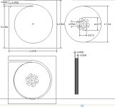
Any hoo, I have attached a picture showing the basic dimensions of a pump using cd-roms as the discs that I'm considering (waiting for some feedback from the TeslaTurbineList on the spacing) If anyone is interested.
-Casey
I have decided that giving a Tesla air pump (you listening nordic😀?) a try would be worth the effort. These things are very efficient, and usually considered when several orders of magnitude more air/pressure are needed. I reason that if it could be a sandblaster at it's optimum 10-50 thousand rpm, it should equal an aquarium pump idling along.
The advantages are:
No pulsations..equivelent to a DC air source.
Infinitely variable
Potentially very quiet..depending on speed.
Any hoo, I have attached a picture showing the basic dimensions of a pump using cd-roms as the discs that I'm considering (waiting for some feedback from the TeslaTurbineList on the spacing) If anyone is interested.
-Casey
Attachments
It seems to me that a hard drive must have all the components you would need for such a pump: multiple platters, precise high speed spindle motor and driver, and a solid metal chassis that can be made airtight. It's not too hard to disassemble a drive to remove the heads and leave the platters free.
The platters would be too far apart as is, but they are kept in place by simple spacers, so it shouldn't be too hard to make thinner spacers. You could probably add more platters as you make the spacing smaller.
I don't understand how those wierdly shaped holes work in the turbine, but I would say that compared to a hard drive, your drawing pictures them closer to the center. What effect does their distance from the center have?
What's your reason for wanting to use CDs as the discs, rather than hard drive platters?
Hi pixpop,
If you do a search online, you’ll find that a HD was used as a donor for a Tesla Turbine (as opposed to a pump). The platters could (and have) been used, but the motor isn’t stout enough. One word… torque. In the HD, it simply needs to get the platters to speed. In a pump the pressure is pushing both ways, that is, if you have 1 PSI out, you also have 1 PSI pushing back on the periphery of the stack.
The involutes’ shape aids in collecting air at the inlet, used as a turbine they are simply holes for the exhaust. You want these as close to the center as you can get them, maximizing the surface area to push the air. The spiral around the discs (not in a HD) in the housing is an annular diffuser to slow the air exiting down to minimize wasted energy in turbulence. Think expansion chamber in a 2-stroke engine exhaust. This is an early draft that doesn’t show the taper, except at the periphery.
I’m lazy 😀. The CD’s are much easier to cut/machine. If I was going for a high speed monster, I would go with a different material, but the polycarb CD’s should handle what I’m asking from them with ease.
-Casey
It seems to me that a hard drive must have all the components you would need for such a pump: multiple platters, precise high speed spindle motor and driver, and a solid metal chassis that can be made airtight.
If you do a search online, you’ll find that a HD was used as a donor for a Tesla Turbine (as opposed to a pump). The platters could (and have) been used, but the motor isn’t stout enough. One word… torque. In the HD, it simply needs to get the platters to speed. In a pump the pressure is pushing both ways, that is, if you have 1 PSI out, you also have 1 PSI pushing back on the periphery of the stack.
I don't understand how those wierdly shaped holes work in the turbine, but I would say that compared to a hard drive, but I would say that compared to a hard drive, your drawing pictures them closer to the center. What effect does their distance from the center have?
The involutes’ shape aids in collecting air at the inlet, used as a turbine they are simply holes for the exhaust. You want these as close to the center as you can get them, maximizing the surface area to push the air. The spiral around the discs (not in a HD) in the housing is an annular diffuser to slow the air exiting down to minimize wasted energy in turbulence. Think expansion chamber in a 2-stroke engine exhaust. This is an early draft that doesn’t show the taper, except at the periphery.
What's your reason for wanting to use CDs as the discs, rather than hard drive platters?
I’m lazy 😀. The CD’s are much easier to cut/machine. If I was going for a high speed monster, I would go with a different material, but the polycarb CD’s should handle what I’m asking from them with ease.
-Casey
I'd extend the stack - you'll need 10 to 15 CDs to do the job, and I found spacing in the stack to be critical.
I'd also make the involute on say the center 8 disks - it reduces air 'bypass'.
So to sum up. The last disk in the stack (at the back) needs to be solid, and the clearance between the front housing and the first disk needs to be small.
The choice of CDs is a good one, and the whole pump will be as quiet as the balancing of the 'blades'. I had good success using an old TT motor, so it should be easy enough to you to get one working... the trick is getting pressure from them.
As a good starting point - use the built in spacers on the CDs, and see where that gets you to.
Have fun
Owen
Hi owen,
Maybe..I'm looking for a pretty weeny output as far as Tesla's go. I also have a little trick up my sleeve to boost output if needed.
Absolutely...and the most debated. The .02" was chosen as a starting point after plugging the numbers into a simplified formula.
The trick to pressure, as I understand it, is slowing the air down enough before it starts compressing in the collector.
The plan is to bodge one together to see if it's close to what I want. If it is I'll refine it.
-Casey
I'd extend the stack - you'll need 10 to 15 CDs to do the job,
Maybe..I'm looking for a pretty weeny output as far as Tesla's go. I also have a little trick up my sleeve to boost output if needed.
I found spacing in the stack to be critical.
Absolutely...and the most debated. The .02" was chosen as a starting point after plugging the numbers into a simplified formula.
so it should be easy enough to you to get one working... the trick is getting pressure from them.
The trick to pressure, as I understand it, is slowing the air down enough before it starts compressing in the collector.
The plan is to bodge one together to see if it's close to what I want. If it is I'll refine it.
-Casey
- Status
- Not open for further replies.
- Home
- Source & Line
- Analogue Source
- Corian Turntable Fun