My LM3886 amp gets pretty warm since there is no good ventilation in the case design. As opposed to just cutting holes in the sides I decided I might try and rig up a computer fan. Easy right? Yes, unless you want it triggered by temperature---Go Go Gadget Arduino!
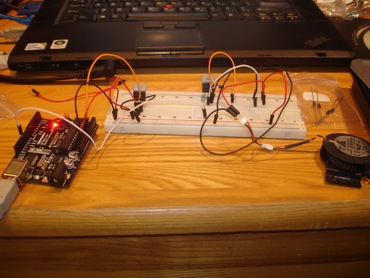
The Arduino is a platform that allows for easy microcontroller tinkering. You can do quite a bit with it and its generally a good time. I built a circut/code that will turn on the fan when the temperature of a sensor(likely mounted on the heatsink) gets above a certain value and then back off at another value (likely less than the on temp). There will also be an LED to warn of a too high temp. Here is the circut (no LED yet) with Arduino connected to my computer.
Anyways, the Arduino needs 9V 500ma (minimum) to run without the computer. This is where I am looking for some advising on how to best approach this given my current amp configuration:
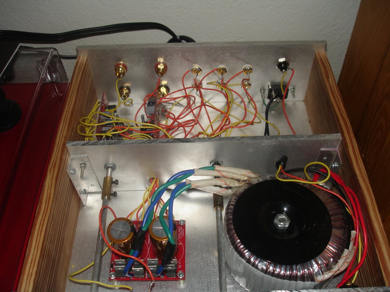
I would like the fan to separate from the power switch so I think that means I will have to take 120v from the inlet port at the back. What should I use to transform/regulate this power to what I need. I was thinking I could just take a walwart type transformer and just hard wire it in. Any reason why this wouldn't work? Any better/different/more interesting options. Will this option have effect on the audio/signal. I am thinking of mounting the fan on the back right side to keep it a bit away from the signal. Transformer would preferably go in the front section.
Disclaimer:I know that I don't really need the computer fans and there are probably great methods for passive cooling but I like tinkering and this is a fun project for me.
Thanks!
The Arduino is a platform that allows for easy microcontroller tinkering. You can do quite a bit with it and its generally a good time. I built a circut/code that will turn on the fan when the temperature of a sensor(likely mounted on the heatsink) gets above a certain value and then back off at another value (likely less than the on temp). There will also be an LED to warn of a too high temp. Here is the circut (no LED yet) with Arduino connected to my computer.
Anyways, the Arduino needs 9V 500ma (minimum) to run without the computer. This is where I am looking for some advising on how to best approach this given my current amp configuration:
I would like the fan to separate from the power switch so I think that means I will have to take 120v from the inlet port at the back. What should I use to transform/regulate this power to what I need. I was thinking I could just take a walwart type transformer and just hard wire it in. Any reason why this wouldn't work? Any better/different/more interesting options. Will this option have effect on the audio/signal. I am thinking of mounting the fan on the back right side to keep it a bit away from the signal. Transformer would preferably go in the front section.
Disclaimer:I know that I don't really need the computer fans and there are probably great methods for passive cooling but I like tinkering and this is a fun project for me.
Thanks!
The σ25 Regulated Power Supply
If you dont like that one, there are dozens of ebay china ones. It would be your best bet. Just set it to 9v via 2 resistors and then you have a filtered regulated setup. Rule of thumb is that you want the vac voltage of your transfomer to match your dc voltage your shooting for. You can go higher (up to 40v higher with a very light load or good heatsinking) but you need to feed the regulator at least 3v higher then the voltage your shooting for.
If you dont like that one, there are dozens of ebay china ones. It would be your best bet. Just set it to 9v via 2 resistors and then you have a filtered regulated setup. Rule of thumb is that you want the vac voltage of your transfomer to match your dc voltage your shooting for. You can go higher (up to 40v higher with a very light load or good heatsinking) but you need to feed the regulator at least 3v higher then the voltage your shooting for.
Don't use a wallwart psu, they're usually switching supplies and generate noise, which might or might not be picked up by you circuit. And with a GC's typical gain of around 20dB this might cause audible annoyance.
I'd take AC from the positive half of the Gainclone's transformer, halfwave rectify (single diode), smoothing cap, maybe even CRC (0R47 or even 1R), pop in an LM7809 (OnSemi has lowest noise figure) and be done. Good for 1A.
Now realizing that you're using chipamps's PSU board...you might be able to use the LED's PSU (single diode plus cap) and pop in the 7809 right there. Just check for maximum V_in of the LM7809 and heatsinking.
As long as you don't drill holes in the case the fans won't help at all with the cooling. They only move the hot air around inside the case and their own heat dissipation adds more to the temperature rise.
There are still wall-warts that are not SMPS. They should do fine.
Quite an effort for an on-off temperature control with hysteresis. A simple temperature switch can do that and it doesn't even need a power supply.
With a microcontroller you could realize continuously variable fan speed with PI control and start boost. Plus an overtemperature protection that cuts the power supply to the amp or reduces the signal level, when the temperature rises in spite of the fan or due to a fan failure. You could also use the fan's feedback signal to check whether it is working or not.
Yes, it is a bit over kill but I dont have much knowledge in the electrial realm and for me writing a code is much more natural and intuitive. If I want the fan to turn on I can write a code that pretty much says, "fan on." Now for others electrical is more intuitive, sadly this is not my case. I will look into temperature sensors but I would like to play with the Arduino especially since as you are saying there is a lot of potential for other stuff.Quite an effort for an on-off temperature control with hysteresis. A simple temperature switch can do that and it doesn't even need a power supply.
With a microcontroller you could realize continuously variable fan speed with PI control and start boost. Plus an overtemperature protection that cuts the power supply to the amp or reduces the signal level, when the temperature rises in spite of the fan or due to a fan failure. You could also use the fan's feedback signal to check whether it is working or not.
As far as holes in the case, I will be drilling intake and exhaust ports but meant to say that I want more than just holes in my case.
As far as powering options, I like the idea of using either a non-smp wall wart or the LED "channel" of the PS board.
There are only 2v across the LED right now but I think there is a resistor before this that changes this (right?). I could take this resistor out(or use a smaller one) and then get ~20v (the output from my transformer). Then I would put in the voltage regulator and run this to my Arduino's input. Does this sound about right?
Since this disapates voltage as heat I will need to heatsink it. Anything special about the heatsink or would it be fine on any recycled sink if the fan blows on it to?
Thanks for the help guys, as I said this electricity knowledge is a work in progress for me.
The LED has only two volts across because of the resistor in front of it, yes. You'll have to tap into the circuit before that resistor, in other words after the diode at the smoothing cap. The voltage there is, as you said, higher. I think a TO220 LM7809 can take 35VDC at it's input (iirc) and just using the amp's case as a heatsink should do. It'll have to be electrically inulated from the chassis though...
Electronics-wise it's recommended to read everything here: DIY Audio Articles, especially the Beginner's Guide and the Power Supply section.
Electronics-wise it's recommended to read everything here: DIY Audio Articles, especially the Beginner's Guide and the Power Supply section.
Last edited:
Awesome, I could just wire the LM7809 in parallel between the cap and the resistor then? This will give the same voltage right? That way I can keep the PS board pretty much untouched just 1 wire going from cap to Vin for the regulator and 1 wire from regulator ground back the resistor. If so i think I can handle that
Is it just me or does drawing an extra 10 watts (20v at 500ma) on one rail and not the other seem like a bad idea? We are not talking about poping an extra led here or some other few ma thing. And we havent factored in the current of the fan.
just 1 wire going from cap to Vin for the regulator and 1 wire from regulator ground back the resistor.
It takes a few capacitors next to the regulator pins.
Is it just me or does drawing an extra 10 watts (20v at 500ma) on one rail and not the other seem like a bad idea?
Not much reason to worry about.
Wow man. I can't believe you went that far to get a temp controlled fan. Look up MIC502 PWM fan controller. I use them all the time. I still have a few of the MIC chips left for various other projects.
I first used them to make a TEC controller for a desktop mini fridge. Only after succeeding in that task I decided to try a few as they were intended. Surprise, they work great for controlling PC fans also.
Just add the proper thermistor network and you are GTG.😉
EDIT:
It should be noted. That schematic is crap. It is not mine. I'm not sure where I found it. That would probably work but I would inclined to use a few diodes and an appropriate inductor to keep from frying the fet/power transistor and to make sure the fan doesn't make funny noises at low RPM.
Attachments
Last edited:
Member
Joined 2002
All this extra stuff to cool a pair of chips, that only need a heat sink per device. Hope all this effort doesn't go to waste, buy injecting "un" wanted noise into the amps.
Good Luck.!
Good Luck.!
- Status
- Not open for further replies.
- Home
- Amplifiers
- Chip Amps
- Cooling fans with Arduino