Allen, I have read that there are 2 ways to get Mms - and 1 way is to add mass to the driver. As I type this, I just realized how I could do this for the Linaeum drivers - by slipping a piece of paper into the center. The trick is to temporarily hold it in place - and to get an accurate measurement of its mass.
Ok. It looks like you're going backward from Vas. Another way with Vas, can you vary the rear enclosure?
I just ordered a Dayton Audio DATS V3 from Parts Express (they have it on sale for $129) and a digital scale they suggested (for $10), so I am hoping I can get the TS data of the Linaeum tweeters.
I am going to measure the TS parameters of the Linaeum TLS tweeters today. Once I get that data, what is the program I should use to design the crossover?
As I have mentioned, I am anticipating that it will be a 4th order Linkwitz Riley design, with the woofer frequency of 440Hz, and the tweeter at 480Hz. My biggest concern is to how I would go about leveling the volume of the tweeter.
As I have mentioned, I am anticipating that it will be a 4th order Linkwitz Riley design, with the woofer frequency of 440Hz, and the tweeter at 480Hz. My biggest concern is to how I would go about leveling the volume of the tweeter.
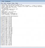
I have measured two of the Linaeum TLS tweeters; the ones from the LS2 speakers, that have the plastic cord suspension. (These are probably the main reason for the different responses; the Fs in particular.)
TLS #1:
Re = 11.9 Ohms
Fs = 95.62 Hz
Qts = 1.315
Qes = 2.593
Qms = 2.667
Le = 0.08055 mH
Mms = 3.25 gm
Vas = 0.00109 cu ft
TLS#2:
Re = 10.26 Ohms
Fs = 82.03 Hz
Qts = 1.002
Qes = 2.413
Qms = 1.715
Le = 0.07817 mH
Mms = 3.442
Vas = 0.00139 cu ft
I am not surprised these are somewhat different - I think they are essentially hand made. Are these differences going to be critical for the crossover design?
Question on the Dayton Audio DATS V3 that I used to measure these - I had to put in a "Piston Diameter" so I used 1 since that is a typical tweeter. Is this going to affect the data?
A bit difference between these was that with TLS#1, I only had to add 1.84gm of added mass, while TLS#2 I had to add 4.57gm in order to shift the Fs by at least 25%. I wonder why this is? Maybe the magnets in TLS#2 are stronger?
Main question: what do I do next? What program should I use to start designing the crossover(s)?
Attachments
Last edited:
You are measuring impedance, that is good. TS parameters are not important here. The difference around the driver resonance is irrelevant here, you can tweak your boxes on a rainy day.
You want four measurements, two each for woofer and tweeter.
One is the impedance of each driver, disconnected from the crossover. The impedance measurement method should be calibrated so you can extract a result in ohms. You then want to save the files as *.zma, one for each driver.
The other is the transfer function. Do separately for woofer and tweeter, the crossover is connected, you measure at the driver terminals. You are aiming to plot the shape of the response. The level is less important, chosen to avoid noise and distortion (somewhere between will do). You save these files as *.frd, response files.
Impedance measured with the DATS V3 - I can do that. But how is that value saved as a *.zma file?
I have my active crossover - how do I measure the transfer function? With the DATS, or with REW? And same question - how does the data get saved to a *.frd file?
Do the .zma and .frd files get used in what program?
I have my active crossover - how do I measure the transfer function? With the DATS, or with REW? And same question - how does the data get saved to a *.frd file?
Do the .zma and .frd files get used in what program?
The zma and frd are simple human readable file formats with columns for frequency, magnitude and phase. You could make them in a text editor, although it is more typical to trace a screenshot with a graph tracer, or save them directly from your measurement program.
Measuring the transfer curve is very similar to measuring the impedance. You don't, however, need the resistors in this case to make a current measurement. Instead, you want to see the Voltage directly off the speaker terminals. However, be careful with the levels because feeding an amplifier output back to your sound card inputs can potentially damage it. A Voltage divider and/or AC coupling, isn't a bad precaution.
You can put all these files into a crossover simulator like Xsim - XSim free crossover designer
EDIT: corrected below
I have installed XSim. I see the Response and Impedance dialogs on the right side. I have the active crossover, so I should do sweeps with REW - but without the PEQ filters, so I get the "raw" driver output, with only the crossover I want applied? How do people do this without any crossover? I am puzzled ...
Okay, so the process is to plot points on a graph? What is the column format? I have never heard of a graph tracer. Does REW save as an FRD file? I wonder if DATS V3 can save the impedance as a ZMA file?
EDIT: I have one of the tweeter's response and impedance files imported into XSim. What is the next step, I should take? I see XSim has first and second order circuit blocks premade - how can I get to a fourth order?
Last edited:
Wait, I was distracted and forgot which way we were going here 😱
You want to measure the output of your line-level crossover, and having the amp or speaker connected is un-necessary. Use RCA connectors to the crossover inputs and outputs (if it is that kind of device).
You want to measure the output of your line-level crossover, and having the amp or speaker connected is un-necessary. Use RCA connectors to the crossover inputs and outputs (if it is that kind of device).
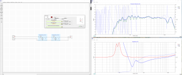
I think I only know enough to be dangerous. Here's what I've got. Should the response curve be the actual raw measurement of the tweeter? Or is this response measured in REW with the active crossover what I want to use?
I just stuck two second order circuit blocks together in series ... oh- the first one was set to 8 ohms. I changed it to 12.33 ohm because that is the approximate impedance of the raw tweeter as displayed in XSim - though this is different than what DATS was reporting for this driver, which is 10.26 ohms.
I just stuck two second order circuit blocks together in series ... oh- the first one was set to 8 ohms. I changed it to 12.33 ohm because that is the approximate impedance of the raw tweeter as displayed in XSim - though this is different than what DATS was reporting for this driver, which is 10.26 ohms.
Attachments
Last edited:
Wait, I was distracted and forgot which way we were going here 😱
You want to measure the output of your line-level crossover, and having the amp or speaker connected is un-necessary. Use RCA connectors to the crossover inputs and outputs (if it is that kind of device).
Okay - the miniDSP 2x4 HD does have RCA inputs and outputs. So, I need to plug the crossover into my computer and measure its output - without the driver EQ?
I am trying to keep up here don't I need to work with the driver's response? As far as I know, the active crossover is a generic Linkwitz Riley 4th order filter. It does that in the digital domain. So measuring it would not seem to be necessary?
On the assumption that the current crossover is correct, then you don't need to know the drivers response, and it saves a lot of time to bypass that part of it.I am trying to keep up here don't I need to work with the driver's response?
Sounds as though it isn't optimised at all then? May have to take a step back and do some response measurements after all. On the other hand we can find just a starting point if you really want to keep moving forward.As far as I know, the active crossover is a generic Linkwitz Riley 4th order filter. It does that in the digital domain.
Hi Allen,
The active crossover is giving me as close to exactly response as I could want. So, it is supremely optimized, as much as is possible. It has essentially flattened all the peaks and rises in each of the drivers response - and then there is an overall PEQ filter applied to the system, which flattens the summed response.
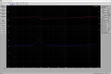
So, the challenge is this - I do not think it is possible to match that precise and focused custom response control, in the analog domain. And certainly I won't be able to do that. Here's the raw drivers on the the crossover, and then the fully EQ'd system.
Actually this is the first version - it had the crossover on the tweeter at 440Hz, and I moved it up to 480Hz, to reduce the rise at the summed crossover point. And I reduced the "room curve" at the bass - this was +1dB/octave below 200Hz, and I have lowered that to 0.7dB/octave. And I have pulled the speakers out into the room ~6" - and added eggcrate foam to the last segment of the MLTL. I will remeasure things soon.
The sharp dip at ~106Hz is a room cancellation, that doesn't occur in the nearfield measurements. I also confirmed that it is a room issue, by putting one of the speakers near the middle of the room, up on a 2' high table and measured the response. It had a completely different set of dips and peaks.
Case in point on my skepticism on being able to get the fine custom control - the tweeter has at least 11 narrow peaks and broad rises that have been truncated. many of them, the SPL decrease is unique. And the dips have been specifically lifted a bit - the most important of which the drop at 10kHz is pushed up to 11kHz, and the dip at 13kHz is lifted maybe 3dB and the response at 20KHz is12dB down instead of 20+.
So, my goal is to do the best analog crossover that I can manage. I think that means starting with what I know about the crossover frequencies and slopes - and then doing the most possible EQ'ing with the least complicated additional components. I have my target response - and the learning curve is steep.
If it doesn't work as well, then so be it. This is my ultimate speaker - the TLS driver is simply amazing, and the MLTL bass is every bit as good, too.
I will learn a lot doing this - and I definitely want to do an analog crossover for the next MLTL I want to build, which will use the Radio Shack made Linaeum tweeter - second order slopes (probably) at somewhere between 1.6kHz and 2kHz (probably).
The active crossover is giving me as close to exactly response as I could want. So, it is supremely optimized, as much as is possible. It has essentially flattened all the peaks and rises in each of the drivers response - and then there is an overall PEQ filter applied to the system, which flattens the summed response.
So, the challenge is this - I do not think it is possible to match that precise and focused custom response control, in the analog domain. And certainly I won't be able to do that. Here's the raw drivers on the the crossover, and then the fully EQ'd system.
Actually this is the first version - it had the crossover on the tweeter at 440Hz, and I moved it up to 480Hz, to reduce the rise at the summed crossover point. And I reduced the "room curve" at the bass - this was +1dB/octave below 200Hz, and I have lowered that to 0.7dB/octave. And I have pulled the speakers out into the room ~6" - and added eggcrate foam to the last segment of the MLTL. I will remeasure things soon.
The sharp dip at ~106Hz is a room cancellation, that doesn't occur in the nearfield measurements. I also confirmed that it is a room issue, by putting one of the speakers near the middle of the room, up on a 2' high table and measured the response. It had a completely different set of dips and peaks.
Case in point on my skepticism on being able to get the fine custom control - the tweeter has at least 11 narrow peaks and broad rises that have been truncated. many of them, the SPL decrease is unique. And the dips have been specifically lifted a bit - the most important of which the drop at 10kHz is pushed up to 11kHz, and the dip at 13kHz is lifted maybe 3dB and the response at 20KHz is12dB down instead of 20+.
So, my goal is to do the best analog crossover that I can manage. I think that means starting with what I know about the crossover frequencies and slopes - and then doing the most possible EQ'ing with the least complicated additional components. I have my target response - and the learning curve is steep.
If it doesn't work as well, then so be it. This is my ultimate speaker - the TLS driver is simply amazing, and the MLTL bass is every bit as good, too.
I will learn a lot doing this - and I definitely want to do an analog crossover for the next MLTL I want to build, which will use the Radio Shack made Linaeum tweeter - second order slopes (probably) at somewhere between 1.6kHz and 2kHz (probably).
Attachments
Last edited:
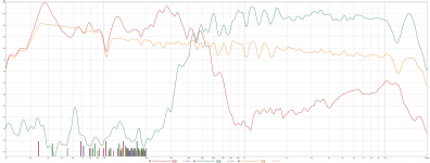
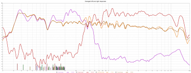
Of course, I found the later measurements I did of both the left and right speakers (the above is just the left speaker). These are the averaged raw woofer responses, and the averaged raw tweeter responses, the averaged left and right response with just the driver PEQ - and the averaged left and right response also with the system PEQ. (But this is with the +1dB/octave on the bass, and without the eggcrate foam, and the current speaker positions).
The overall response is smoother and more even. This is a very high bar, I think, to aim for with an analog crossover.
The overall response is smoother and more even. This is a very high bar, I think, to aim for with an analog crossover.
Attachments
Unless I'm mistaken, you are wanting the crossing and the equalising to done by the passive components?
Can you do 7 plots. Either post separate plots so we can trace them or do frd and zma.
Woofer impedance, raw response, after cross, Tweeter impedance, raw response, after cross and total response.. like shown above only on separate screenshots, with scale visible and zoomed around +3/-30dB.
Can you do 7 plots. Either post separate plots so we can trace them or do frd and zma.
Woofer impedance, raw response, after cross, Tweeter impedance, raw response, after cross and total response.. like shown above only on separate screenshots, with scale visible and zoomed around +3/-30dB.
Okay, that is the plan.
If I can get it working as an analog setup, then yes, it would need to be equalized as part of that.
If I can get it working as an analog setup, then yes, it would need to be equalized as part of that.
For sure - I did find that DATS v3 can export the impedance file, and REW can export .TXT files in the right format.
- Home
- Loudspeakers
- Multi-Way
- Converting Linaeum LT1000 from active to passive