I have 2 pairs of 4-ohm bass drivers. I plan to build a pair of floor-standing enclosure with a pair of the woofers per cabinet. The problem is if I’m gonna safe the amp I have to wire the woofers in series to bring an impedance to 8 ohms. But the inductor values for a crossover is going too high. Said if the crossover point is below 200Hz, the inductor for a simple second-order filter will be exceeded 10mH. So, can I do like this? If I’m going to add a resistor in parallel with the series wiring woofers, in order to half the impedance to 4 ohms. Does anyone has experience with this? What is the result? Thank you in advance.
Yes, you should certainly not do this!
If you supply details of (links to) all your drivers - woofers? mids? tweeters? - we may be able to supply a more workable solution.
If you supply details of (links to) all your drivers - woofers? mids? tweeters? - we may be able to supply a more workable solution.
If it was a good idea, then I'd be happy to explain how to do it safely. However I do agree that it is not a good idea in this case.please do not do this.
[As a side note, using a resistor in parallel with a load to maintain a minimum current, or to reduce the size of the inductor, is used elsewhere in electronics.]
I see the schematic of JBL L-112. They placed a 51-ohm resistor parallel with the woofer alone. Could anyone please explain what is the reason to do like this? And why, in my case, I shouldn’t do the same?
https://encrypted-tbn0.gstatic.com/...H2MdwsoUZNEMDEgO8OCd9kNaVLkB7K61bVwMXGO9ATh4Q
https://encrypted-tbn0.gstatic.com/...H2MdwsoUZNEMDEgO8OCd9kNaVLkB7K61bVwMXGO9ATh4Q
I guess JBL did this to improve the filter at high frequencies, to ensure the single inductor can reduce levels near breakup.
Briefly, a 51 ohm resistor will draw very little power from the amp compared to the parallel 4/8 ohm woofer.
You wanted to put an 8 ohm resistor in parallel with your 8 ohm in series woofers, in which case a large amount of power (half of the total) would be wasted in the resistor.
For a 100W amp, say, you would require a resistor capable of dissipating 50W of power without running hot. A suitably heat sinked resistor would be required!
A single resistor would need to dissipate about the same wattage as the woofer pair, which could be a problem since even a 20-watt rating might be insufficient. But you could simply use multiple resistors, in parallel or series-parallel, to handle the power safely. Use as many resistors of an appropriate value/rating as needed to reach a safe power handling capacity. But it is difficult to say what power rating would be "safe". Since the crossover is going to be 200 Hz that means the woofers (and parallel resistors) only need to handle the low frequencies. But depending on the type of music played it may still be a large portion of the amplifier output. If you know the maximum expected power you can design for that. The resistors don't need to dissipate the full output power.
Consider designing for a non-standard impedance. Maybe a 6-ohm low pass would be enough to bring the inductor value down to a reasonable size. Then you would need only 24 ohms of resistance in parallel with the 8 ohms (4+4) of driver impedance. This would also waste less amplifier power. You are free to choose any impedance that makes the crossover values reasonable. Also, check the impedance curve of your woofers to find out what the impedance actually is at 200Hz. It might not be 4 ohms at that frequency.
Consider designing for a non-standard impedance. Maybe a 6-ohm low pass would be enough to bring the inductor value down to a reasonable size. Then you would need only 24 ohms of resistance in parallel with the 8 ohms (4+4) of driver impedance. This would also waste less amplifier power. You are free to choose any impedance that makes the crossover values reasonable. Also, check the impedance curve of your woofers to find out what the impedance actually is at 200Hz. It might not be 4 ohms at that frequency.
Yes, presscot has not responded to the request for details of his drivers I made in post #3. There's little point in further discussion until more information is supplied.And the project specs and drivers are?
The following are the drivers to be used:
Woofer: 10” SEAS SW250; SW 250/1 L0019-04S
Mid-woofer: 6.5” SEAS H602; http://www.seas.no/images/stories/vintage/pdfdataheet/h0602_p17rexp.pdf
Midrange: 2” Visaton G-50FFL (optional); G 50 FFL - 8 Ohm | Visaton
Tweeter: 1” SEAS Millennium; E0011-06 T25CF002
At the moment, it is still in the process of deciding which way to go between 3-way and 4-way. If it is 3-way, the crossover point may be picked around 170 and 2,500 Hz. But if it was 4-way, then, the crossover point might be around 170, 800 and 4,000 Hz. Every section of the crossover would be jointed by the second order filters. That’s all my plans for now. Thank you
Last edited:
You need to simulate this thing and if you managed to do that correctly, you would have then realized what to expect of it. A lot of work by all means. Good luck!
That particular woofer is well above 4 ohms near your crossover frequency due to high voice coil inductance. The minimum impedance above resonance is about 5 ohms at 80 Hz. That is based on the data sheet and the free air resonance will change when those woofers are put in an enclosure. By 200 Hz the impedance increases to around 8 ohms, and the impedance is ramping up rapidly. It would be best to use a Zobel across the woofers to flatten that impedance rise in order to get an accurate crossover response.
But your idea to use parallel resistance might still work good enough for your purpose.
At 170 Hz the woofer impedance appears to be under 8 ohms, perhaps about 7.5 or so. There is no mark at 170 Hz, I am estimating from the graph. A pair in series would be about 15 ohms at your crossover frequency. If you want to bring that down to 4 ohms for your crossover you need about 5.5 ohms in parallel. Four 22-ohm resistors could provide that, or six 33-ohm resistors. This has several implications. The resistors will, in total, dissipate more power than the actual woofers, and the resistance will counteract the rising impedance of the woofers, The crossover will see a predominantly resistive load, so a Zobel would not improve things very much at this point. Of course the resistors should be capable of dissipating quite a lot of power, perhaps 10 or 20 watts each. If these are difficult to source you must choose different values and divide the power up accordingly. And, if extended high power operation is expected choose according to the amplifier's capability.
Other considerations:
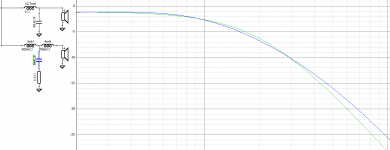
Asking the H602 to operate down to 170 Hz may be a bit optimistic. The crossover expense for the woofer will be mostly duplicated at the low end of the midwoofer, unless you use the natural rolloff of the midwoofer and its sub-enclosure. The H602 is a low QTS woofer and the graph is showing rolloff beginning well above 200 Hz. A higher crossover point than 170 Hz may produce a better match, perhaps in the vicinity of 250-300 Hz. This will also reduce the inductor size, which could eliminate the need to reduce the impedance of the subwoofer section. A Zobel would be desirable instead.
I suggest modeling the H602 in its sub-enclosure first to get a better idea of its low end response in the system, then design for the nest match with the SW250 combo.
stevebogus, thanks for giving me good advises. The idea of using H602 with its natural roll-off frequency is interesting. I’m a beginner for the speaker building and not have much experience of the enclosure design.
As suggested by the online calculator, the H602 is suited with ported enclosure. If I’m going to build the H602 to operate only for mid-bass, for the sub-enclosure design, do I have to port the cabinet? Can I simply use a simple closed enclosure? Thank you.
As suggested by the online calculator, the H602 is suited with ported enclosure. If I’m going to build the H602 to operate only for mid-bass, for the sub-enclosure design, do I have to port the cabinet? Can I simply use a simple closed enclosure? Thank you.
Last edited:
It could be a challenge. If you put the H0602 in a smaller closed box, the Q rises to 0.7 by 100Hz resonance. A natural rolloff any higher is going to have a peak in the response. Putting it in a larger closed box, you may be left wanting to cut the low end in the crossover to improve power handling.
Maybe this is leaning toward a crossover being the most straightforward lower rolloff for this driver, meaning to also put it into a middle of the road enclosure.
Ported is not always the best choice for a mid driver, it could result in more delay in the midrange, and the impedance peaks may need more attention in the crossover.
Last year I built a 4 way using an active crossover. It can be done for about the same cost of a good passive crossover. I used the miniDSP digital crossover, six channels of the LM3886 chip amps from Ebay and woofer amps from Parts Express. The impedance problems go away and you can focus on really getting the crossover perfect as it is so easy to adjust. Considering what you have invested in drivers, you would do well to make it active.
A couple of thought. 1) Make it a 3-way as the tweeter you selected will be fine to 2.5k with a 4th order (acoustic) crossover and the 6.5" mid will be fine to 2.5k. 2) where ever you choose the cross to the woofer, put a high pass filter on the mid. Using the box natural 2nd order roll off will still mean that excursion would be significant below resonance. Acoustically the output will roll off at 12dB/oct, excursion will asymptote to constant vs frequency. While not "heard" this excursion can result in significant distortion in the midrange. 3) Go fully active 3-way or hybrid 3-way with active between woofer and mid and passive between mid and tweeter.
- Home
- Loudspeakers
- Multi-Way
- Converting driver impedance