I always appreciate your responses Allen, but this concept is a little above me so I might have to keep it simple. I am not even too worried about totally copying the passive network, it might just help as a guide to what needs to be done with the biquads.Why wouldn't you measure at the driver terminals?
I think I will take the VituixCad route, measure use biquads. I could potentially try and copy the passive network into VituixCad and save the transfer function as an overlay like Dcibel mentioned but I even that I need to get my head around that first.
Yes, it's something to get ones head around but straight measuring at the driver terminals does give the correct transfer function. It's also the only way to do it in one step. Of course I wouldn't begrudge anyone wanting to approach all this from a different angle.
See what it could offer though, for what it's worth.. because even though approaching the crossover from scratch would be a good thing, you'll then need to do several measurements. This is what your choice comes down to as I see it, because on the other hand the existing passive crossover already includes the integration work done by the original designers. It may not be perfect.. but copying manufacturer data or taking simple response measurements can also be imperfect.I am not even too worried about totally copying the passive network,
Is there an article or something on how to measure at drivers terminals? Or what do I Google?Yes, it's something to get ones head around but straight measuring at the driver terminals does give the correct transfer function. It's also the only way to do it in one step. Of course I wouldn't begrudge anyone wanting to approach all this from a different angle.
See what it could offer though, for what it's worth.. because even though approaching the crossover from scratch would be a good thing, you'll then need to do several measurements. This is what your choice comes down to as I see it, because on the other hand the existing passive crossover already includes the integration work done by the original designers. It may not be perfect.. but copying manufacturer data or taking simple response measurements can also be imperfect.
If you've measured impedance before then you've used wire terminals rather than a microphone. In this case you don't even need the current source resistors, it's the most direct type of measurement you can do over a band of frequencies using a program like HolmImpulse or REW or Arta.
You're measuring the voltage across the speaker per frequency. You can use either pink noise or a swept sine. The level you use isn't critical as long as you use the same for each driver, and stay off the noise floor.
* The main concern you'll have is not overdriving the sound card input and causing damage (or distortion). This is a common procedure, eg remember that the amp output will be low enough only if you don't turn it up too far. Some are careful and use an L-pad attenuator or a buffer, and maybe even capacitor coupling. Look for DC on the amp, don't encourage pops and crackles by making poor connections, ensure you do the right thing with ground if you connect it at all to the output. Since ground is shared with the amp via the RCAs coming from the soundcard out to supply the amp with its signal, it isn't always necessary to connect it to the amp running back to the soundcard input.
Last edited:
Member
Joined 2003
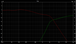
Just right click on most any plot line in VituixCAD, then "save selected as overlay". For example, here is a filter transfer function for a basic 2-way speaker:Could you also tell me what you mean by saving the transfer function as an overlay?
Thats fine the goal isn't a perfect duplication, I just want to use it to see how the original design was executed and for me to try and emulate it to a certain degree.
View attachment 1028380
With that transfer function saved as an overlay, I simply insert active filter blocks and attempt to reproduce it. I spent 5 minutes and got in the ballpark with only a couple blocks. These parameters can either be copied directly over to the DSP software, or right click on each block and "copy biquad coefficients" to grab the biquad values directly as plain text.
Attachments

Apoligze guys I had Covid, and I was deep into a Audio trance pushing hard to comprehend these concepts and got hit and have been down and out for about 6 weeks, I only just trying to refresh everything in my mind that was going on this thread.
I right clicked and saved all as overlay but nothing happened. What do I do then? If I understood correctly, I am using the passive crossover to use as a model and adding biquads instead of the crossover components after I saved as overlay then chossing Hypex DSP in options and making a new schematic?
I designed the crossover and have charts and graphs all over the place, so I am half way there but on the SPL graph I dont have 3 driver FR's showing, although it did originally when I connected the crossover. Perphaps I just need to click on something? I added impedance from Dats 3 of each driver. Anything left for the preliminary stage?
Sorry for so many questions, this will get me going and I will also look into the Vituixcad thread.
Dcibel it seems your way might be a really simple way for me to laern Vituixcad and simultaneously model the passive crossover. Unfrotunately your link isn't working and I can't put two and two together comparing the passice crossover and the Biquad examples you shown below.Just right click on most any plot line in VituixCAD, then "save selected as overlay". For example, here is a filter transfer function for a basic 2-way speaker:
View attachment 1028380
I right clicked and saved all as overlay but nothing happened. What do I do then? If I understood correctly, I am using the passive crossover to use as a model and adding biquads instead of the crossover components after I saved as overlay then chossing Hypex DSP in options and making a new schematic?
Now, do I need to measure frequency repsonse of each speaker and upload into Vituixcad?With that transfer function saved as an overlay, I simply insert active filter blocks and attempt to reproduce it. I spent 5 minutes and got in the ballpark with only a couple blocks. These parameters can either be copied directly over to the DSP software, or right click on each block and "copy biquad coefficients" to grab the biquad values directly as plain text.
I designed the crossover and have charts and graphs all over the place, so I am half way there but on the SPL graph I dont have 3 driver FR's showing, although it did originally when I connected the crossover. Perphaps I just need to click on something? I added impedance from Dats 3 of each driver. Anything left for the preliminary stage?
Sorry for so many questions, this will get me going and I will also look into the Vituixcad thread.
Last edited:
AllenB, I appreaciate your response I always learn something new but I can't imagine how a measurement from the terminals will give me a frequency response? Or it doesn't and the impedance sweep is all I need?If you've measured impedance before then you've used wire terminals rather than a microphone. In this case you don't even need the current source resistors, it's the most direct type of measurement you can do over a band of frequencies using a program like HolmImpulse or REW or Arta.
You're measuring the voltage across the speaker per frequency. You can use either pink noise or a swept sine. The level you use isn't critical as long as you use the same for each driver, and stay off the noise floor.
* The main concern you'll have is not overdriving the sound card input and causing damage (or distortion). This is a common procedure, eg remember that the amp output will be low enough only if you don't turn it up too far. Some are careful and use an L-pad attenuator or a buffer, and maybe even capacitor coupling. Look for DC on the amp, don't encourage pops and crackles by making poor connections, ensure you do the right thing with ground if you connect it at all to the output. Since ground is shared with the amp via the RCAs coming from the soundcard out to supply the amp with its signal, it isn't always necessary to connect it to the amp running back to the soundcard input.
I did see instructions on the REW manual on how to take an impedance sweep with REW and a soundcard I am guessing that is the way its done and I will follow that, a little confusing but something I will learn sooner or later.
Can I use Dats and transfer the file or that doesn't work?
It doesn't show you the response that you hear, it shows you the response of the filter. You are measuring the voltage, not the impedance. This is all you need to know to make another filter which matches it.
You need to run the sweep with the crossover in place.
If this is not something you want to do there are other ways that don't involve measurement.
You need to run the sweep with the crossover in place.
If this is not something you want to do there are other ways that don't involve measurement.
- Home
- Loudspeakers
- Multi-Way
- Converting Crossover Schematic To DSP Filters