oh yeah and the DACMAGIC board comes with all components still on, for £20 plus £5 postage, is this reasonable, or pushing it? Would it be a large step up from this DD82?
harrygrey382 said:oh yeah and the DACMAGIC board comes with all components still on, for £20 plus £5 postage, is this reasonable, or pushing it? Would it be a large step up from this DD82?
I think that it's more than it's worth but these kind of things usually fetch more than they should because anything vaguely DIY seems to induce a kind of fever. I have to admit that I've been guilty of that myself and, in a way, it's a sign that our hobby is thriving! Look at how much DACmagics go for, also consider which version they are and then consider how much a case and three transformers would cost you. The decision is yours.
Also remember, it's the first version which is reputed to be the least preferred. (I have no personal experience.) From memory, I think that later models had more regulated supplies and even gold plated boards at the end. A quick Google will put you right I think. I'll try to find that PDF. It's interesting reading anyway.
Regards,
Martin.
Originally posted by harrygrey382
Ok so connect the PSU at required voltage (trial and error measuring the voltage at what I think are power in pins on DAC board?)
What is on the PSU board? Transformer, diodes, capacitors.....what about regulators? If the regulators are on the PSU board - that's makes things very easy. If not, you will have to add some regulation to get the required voltages for the DAC board.
Once you have established that you have the required voltages, you can then determine where they are required by following the PCB traces back from the relevant chips to the connector on the PCB. Download the datasheet for each chip and locate the supply pin...then follow its trace...............
Most of the chips should require +5V, with the opamps needing something like +/-15V
Originally posted by harrygrey382
Connect the digital in (might leave optical till later, all sources coax at the mo), again by same method of measuring (not using a multimeter as found it can't measure digital output, but an optical source lead with the ouput connected to the digital in of PC card, so I here when I've got the right pins?)
Where is the digital input? Is it on this DAC board or on another board?
Originally posted by harrygrey382
And like wise for analoge out.
Will this work, or is there a better way?
You can trace the analogue out back from the RCA connectors.
The link for the DACmagic PDF seems to be dead. I have a copy but it is slightly too big to upload (100Kb). P.M. me if you want it by Email or I could host it somewhere.
This link gives useful details of each DACmagic revision and a 'topless' photo: http://www.gbaudio.co.uk/data/dac2.htm
Regards,
Martin.
This link gives useful details of each DACmagic revision and a 'topless' photo: http://www.gbaudio.co.uk/data/dac2.htm
Regards,
Martin.
harrygrey382 said:oh yeah and the DACMAGIC board comes with all components still on, for £20 plus £5 postage, is this reasonable, or pushing it? Would it be a large step up from this DD82?
TDA1305 vs SM5840/SAA7350/TDA1547 ? The gang of three knock the '1305 into a cocked hat. And that is before you stop to consider the many possible ways in which trio can be significantly modified to tailor the sound. Changing the digital filter or using the SAA7350 without the TDA1547 are just two possibilities.
about regulators? If the regulators are on the PSU board - that's makes things very easy
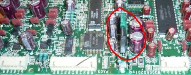
Yes I think it does have regulators, see the pic below, they are D1762 and D1105. Can't I just measure off what voltages come off the main board and then recreate them? Does the presence of regulaters mean I can give it one voltage?
Where is the digital input? Is it on this DAC board or on another board?
The acutal input socket is on the main board, would doing a continuity test between it and the DAC board pins work? Or would there be other things inbetween?
Likewise for analogue out
Attachments
yeah seen that one, it's good. I'm being slow here, but why would I need 3 transformers? Wouldn't one with a regulator etc. circuit be enough?
Before anything else you have to find the digital i/o chips. The will probably be connected to some sort of switching matrix. The matrix will select between the output of the AKM adc and the digital receiver for recording purposes and the input of the SM5840 digital filter and the digital transmitter for playback purposes. To get it all to work you will have to cross connect.
Originally posted by rfbrw
TDA1305 vs SM5840/SAA7350/TDA1547 ? The gang of three knock the '1305 into a cocked hat. And that is before you stop to consider the many possible ways in which trio can be significantly modified to tailor the sound. Changing the digital filter or using the SAA7350 without the TDA1547 are just two possibilities.
This gets my vote as well.
Originally posted by harrygrey382
Yes I think it does have regulators, see the pic below, they are D1762 and D1105. Can't I just measure off what voltages come off the main board and then recreate them? Does the presence of regulaters mean I can give it one voltage?
I didn't notice them before. Yes - measure the voltages going into the DAC PCB and comiing out of the PSU PCB. If they match - then there is nothing happening in between and you can probably use the existing PSU.
So you're saying the SAA7350 combo has more potential? That gives me enthusiasm to persue it.
I've measure the voltages, at PSU there is a multipin plug. Out of a number of choices, there is +12, -12, 5 and GND. The 12s measure 15V, the 5 measures 10V. At the DAC baord input, the pin marked 5 measures 5V, the pin marked 12 measures 12V. So I suppose there's some regulating going on somewhere.
This means I'd need to make a circuit that regulated these two to their correct voltaes. Is this easy?
Also, How much of a deal are these digital i/o chips, I'm having problems locating them
harrygrey382 said:
Also, How much of a deal are these digital i/o chips, I'm having problems locating them
They are what one could call a deal breaker. Without them you cannot connect your co-ax or optical digital sources.
harrygrey382 said:OK, how do I go about that? Do you know a likely chip number, or likely position?
CS8404
CS8412
CXD1076
PCF2705
PCF3523
TC9231
TC9245
TC9271
SAA7274
TDA1315
TDA1373
YM3623
hmm, can't find any of them, certainly not on the DAC board. On the digital circuit board there are LOTS of SAA20** chips, and a CXA1331 on the main board. Will I have to trace the coax sockets back then? Otherwise, what does digital i/o chip cost?
Originally posted by harrygrey382 I've measure the voltages, at PSU there is a multipin plug. Out of a number of choices, there is +12, -12, 5 and GND. The 12s measure 15V, the 5 measures 10V. At the DAC baord input, the pin marked 5 measures 5V, the pin marked 12 measures 12V. So I suppose there's some regulating going on somewhere.
I assume that the PSU plugs into the main board.....then the main board has a cable that plugs into the DAC board. This, with the values you reported above, suggest that there are regulators on the main board. If this is the case - maybe you should consider retaining the main board (if it is not too big).
Originally posted by harrygrey382
This means I'd need to make a circuit that regulated these two to their correct voltaes. Is this easy?
Yes - it is relatively easy - and you could add extra filtration while you are at it - to improve the supply.
Originally posted by harrygrey382
Also, How much of a deal are these digital i/o chips, I'm having problems locating them
Another incentive to retain the main board.
As stated earlier - it all depends on how much work you want to undertake on this. You really have three options:-
1. Use it as it is and make space beside your computer for the big DD82 case.
2. Remove the PSU, mainboard and DAC board from the DD82 - find a neat way to cobble them together in a smaller case - and you are done.
3. Remove the PSU and DAC board from the DD82 - fit them together in an even smaller case - but you will need to build a board with pre-regulators for the DAC board - and build a board for a receiver chip.
Option 2 looks attractive.
harrygrey382 said:On the digital circuit board there are LOTS of SAA20** chips, and a CXA1331 on the main board.
The SAA2003 may provide the digital output but the information I have on the CXA1331 states it is a Dolby B/C noise reduction chip.
yes I'd tend to agree, but two problems, firstly the main board is huge, but I can live with this. The second would be, how do I make sure it's always running in 'monitor mode'? When I turn the whole unit on, it is in play mode, I then need to press a button on in the display which changes it to monitor, then it acts as a DAC. If I could make it always run like this I might stop there.2. Remove the PSU, mainboard and DAC board from the DD82 - find a neat way to cobble them together in a smaller case - and you are done.
It hasn't got SAA2003, closest to that in jnumbers is SAA2001, also with SAA20011, SAA20031 SAA20041 SAA20051 PC74HC4046AT a Mitsubishi M51581 and a 'Japan 41464AJ-08'
Any luck there?
harrygrey382 said:how do I make sure it's always running in 'monitor mode'? When I turn the whole unit on, it is in play mode, I then need to press a button on in the display which changes it to monitor, then it acts as a DAC. If I could make it always run like this I might stop there.
It should be possible to permanently activate "monitor" mode by locating the chip and pin that the switch is connected to.....but locating it will be the problem.
- Status
- Not open for further replies.
- Home
- Source & Line
- Digital Source
- Converting a DAC