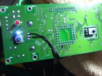
I finally got my 400xi converted the "hard" way😉
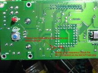
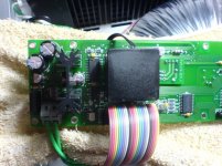
I used a 555 timer to build a small astable circuit, feeding the 68CH11 microcontroller with a ~60Hz pulse signal. My 400xi can be turned on normally and every function works now! 😀
Thanks to philbyx and iampivot for providing the crucial info.
I used a 555 timer to build a small astable circuit, feeding the 68CH11 microcontroller with a ~60Hz pulse signal. My 400xi can be turned on normally and every function works now! 😀
Thanks to philbyx and iampivot for providing the crucial info.

I used a 555 timer to build a small astable circuit, feeding the 68CH11 microcontroller with a ~60Hz pulse signal. My 400xi can be turned on normally and every function works now!
Hi stevexyz:
I have the same problem and i build programable oscillator but no power on, please can you send me the diagram where you connect this new element with voltages and component please.
I connect in the extal pin but nothig, please send me a diagram of your circuit and where you connect
I really appreciate your help
Omar
Dear Stevexyz and Jampivot:
I connect the cicuit like your diagram and the amplifier power on but the S1 input has not light and if you connect signal has no output by speakers. Do you known if is possible the amplifier is bad and this input has short circuit by example and the microchip is testing and power off the amplifier and power on every 18 seconds.
The situation is very rare because i check the signal and the circuit is given 60hertz and the amplifier power on but every 18 seconds power off/on/off/on.......... like mencioned before the S1 has no light and no output if you connect signal, the other work well but the amplifier not maintain power on.
Some idea ?
Is possible take a copy of service manual or schematics ?
Regards
Not quite sure what's wrong with your amp. but you need to cut the original circuit (the one that's feeding the power line frequency to the IC) before you connect your oscillator. You also need to power your oscillator. I used the onboard 5v supply so I don't need to use any external power.
Dear Stevexyz:
Yes, is connected by this way, but the amplifier power on and off every 18 seconds, i think the S1 imput has something bad and the microchip is sensing the problem.
Some idea where take the service manual?
Regards
Omar
Yes, is connected by this way, but the amplifier power on and off every 18 seconds, i think the S1 imput has something bad and the microchip is sensing the problem.
Some idea where take the service manual?
Regards
Omar
Well, maybe your oscillator is not very stable at 60Hz, or there might be something wrong with your amp. You might want to check your oscillator first.
Hi:
Curiosly if i put the switches to 212(120v) and connect to 110volts transformer the remote controler works and some function also for a while but if i put to 222(240v) or 221(220v) the remote control no work and the system is more inestable.
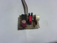
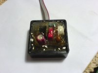
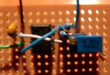
Here is my oscillator made with a pic, normaly more precise but my tester show 61hz.
Curiosly if i put the switches to 212(120v) and connect to 110volts transformer the remote controler works and some function also for a while but if i put to 222(240v) or 221(220v) the remote control no work and the system is more inestable.
Here is my oscillator made with a pic, normaly more precise but my tester show 61hz.
Attachments
Dear Stevexyz:
Are you using 1% precision components and have one potentiometer in you r circuit?
Regards
Omar
Are you using 1% precision components and have one potentiometer in you r circuit?
Regards
Omar
Yeah, I use a potentiometer to vary the input frequency until my amp powered up normally. I'm not quite sure the exact frequency because I don't have a scope, but according to the formula, once I increase the input frequency to some point or higher, my amp will power up normally. You can try it out and see if it works for you. I used a 555 timer circuit. Just do a little google search you should be able to find out lots of websites have the circuit diagram with all components listed and calculation formula.
When the amp senses the frequency is wrong, it doesn't turn on at all. I'm not sure if it senses the frequency after startup as well though.
I'd have to say even though I gave warnings about doing the software hack, I still think it's less dangerous than doing a software hack..
For measuring frequencies, you only need a multimeter that can count frequencies as well, they should be pretty cheap.
I'd have to say even though I gave warnings about doing the software hack, I still think it's less dangerous than doing a software hack..
For measuring frequencies, you only need a multimeter that can count frequencies as well, they should be pretty cheap.
- Status
- Not open for further replies.
- Home
- Amplifiers
- Solid State
- Convert Krell 300iL to European voltage