I have mounted tons of amps using Hypex / Purifi modules and others...
It is much easier to use 220V leds (110V in your case)
Just plug it to the IEC connectors with a Power switch and done )
Checkout :
BeMatik - Lampe Voyant LED 8mm 220VAC Pilote de Couleur Bleu 10-Pack : Amazon.fr: Commerce, Industrie et Science
GUUZI 6pcs 220V-230V 6mm LED Panneau Pilote Dash Avertissement Voyant Lampe Voiture Van Bateau Indicateur Lampe Lampe Pilote Dash Ampoules Directionnelles (Rouge/Bleu/Blanc) : Amazon.fr: Auto et Moto
result :
Last edited:
Hi NBPK402,
I'm having a hard time figuring why you want an LED to indicate 'power button pressed', since the 'power on' LEDs will immediately change whenever the power button is pressed.
And please do heed member Fahey's correction on setting a V-regulator to an 'exact' LED forward voltage. There are two problems with that:
- both the regulator and the LED vary over temperature
- every regulator requires some finite time to stabilize
LEDs hate overcurrent, even if it only lasts a few 10's of microseconds.
Just use the series limiting resistor. 😀
Cheers
The reason is... I am running one led per amp and both amps are turned on via one switch. I want to know if there is a failure of each individual amp. I one of my amps I am running 6 125asx BTL amps and each one goes to a single woofer, and each speaker cabinet has 2 woofers which are crossed over at the same frequency. If one amp fails... I want to know which one it is by looking at the LEDs.
Would these be good to use?
Metal film fixed resistor
Power 1 watt
Resistance 39k ohm
Tolerance 1%
This is what I had bought...if this is not good for this purpose I will wire as suggested above with resisters inline.
5pcs XL4015 5A DC Buck Step Down Voltage Converter Constant Current Power Module 845832027999 | eBay
Last edited:
I have a bunch of the old TDK ones... I assume they would work the same and do not go bad over the years, correct?Yes <ferrite> ))
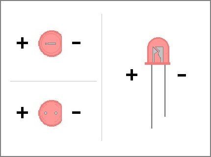
Well I just found out that the info I was given on the resistors was incorrect...which means the ones Parts express sent me were wrong. According to the Amp Camp build insteuctions... I need 10k ohm resistors. I will now order those and hookup via the thermo pin as suggested. Does the positive side of the resistor (long side) go to the thermo pin, and the negative to any ground on the board?
I have the 10k resistors...are these sensative to heat? Any precautions I need to be aware of when soldering them? Do they gi on the positive side of the LED?
It's perfectly reasonable to have one LED per amp channel. But that won't require separate power supplies. In fact, using a separate supply makes less it LESS likely that the indication (which LEDs are ON, which are OFF) will be meaningful.
What I don't understand is why you want to have an LED indicate each press of the power button. That's the only reason to need an Always On, auxiliary power supply.
Your questions on posts 27 and 28 have me a little concerned -- I've never seen a resistor with different length leads (from the factory) -- there would be no reason. In normal operation a resistor dissipates heat; they are not considered to be 'sensitive to heat'. Using a 10k resistor will probably only dimly light the LED (you may not even be able to see it in a darkened room). The original spec was for it to connect to a power supply 'main rail', was it not? If the *thermo pin* is a typical logic voltage, not enough current will reach the LED.
Please measure the *thermo pin* voltage under both conditions -- Amp channel ON and amp channel OFF -- and report them here. Then a suitable resistor value can be suggested.
Cheers
It's perfectly reasonable to have one LED per amp channel. But that won't require separate power supplies. In fact, using a separate supply makes less it LESS likely that the indication (which LEDs are ON, which are OFF) will be meaningful.
What I don't understand is why you want to have an LED indicate each press of the power button. That's the only reason to need an Always On, auxiliary power supply.
Your questions on posts 27 and 28 have me a little concerned -- I've never seen a resistor with different length leads (from the factory) -- there would be no reason. In normal operation a resistor dissipates heat; they are not considered to be 'sensitive to heat'. Using a 10k resistor will probably only dimly light the LED (you may not even be able to see it in a darkened room). The original spec was for it to connect to a power supply 'main rail', was it not? If the *thermo pin* is a typical logic voltage, not enough current will reach the LED.
Please measure the *thermo pin* voltage under both conditions -- Amp channel ON and amp channel OFF -- and report them here. Then a suitable resistor value can be suggested.
Cheers
As per my post here (Convert 120v to 12v for LEDs), the 'thermo pin' I assume is the Thermal Monitor Pin which is high at 5V.
It's perfectly reasonable to have one LED per amp channel. But that won't require separate power supplies. In fact, using a separate supply makes less it LESS likely that the indication (which LEDs are ON, which are OFF) will be meaningful.
What I don't understand is why you want to have an LED indicate each press of the power button. That's the only reason to need an Always On, auxiliary power supply.
Your questions on posts 27 and 28 have me a little concerned -- I've never seen a resistor with different length leads (from the factory) -- there would be no reason. In normal operation a resistor dissipates heat; they are not considered to be 'sensitive to heat'. Using a 10k resistor will probably only dimly light the LED (you may not even be able to see it in a darkened room). The original spec was for it to connect to a power supply 'main rail', was it not? If the *thermo pin* is a typical logic voltage, not enough current will reach the LED.
Please measure the *thermo pin* voltage under both conditions -- Amp channel ON and amp channel OFF -- and report them here. Then a suitable resistor value can be suggested.
Cheers
What I meant was the LED leads...one is longer.
I will get the readings once I get the amp powered up. The 10k resistors were for using 24v, and I believe the thermal is 5v, so yeah I will need a smaller one.
So, in effect, the talk about a few power indicator LEDs runs from march 18th till today august 29th 😉
Said the snail 
Hey!!!! Cheer up!!!!
Cable threads take much longer with even less useful results! 😀
Hey!!!! Cheer up!!!!
Cable threads take much longer with even less useful results! 😀
I expected this to go much faster but with COVID... it has taken me 8 months to get the amp case completed by a friend who is a machinist here in México, and every time I think I am ready something comes up to delay the process longer.
Well I finally got the first amp together and the LED wired up...I purchased a DV power supply and used a Fluke Multimeter to measure the voltage with and without the Buck down board. I brought the voltage down tonthe spec for the LED and ussd a 10k resistor.
Attachments
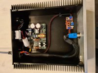
Very nice construction! Easy to see why it took some time to complete!
By 'brought the voltage down to the spec for the LED', do you mean the LED's rated forward voltage? If so, the 10k series resistor likely won't provide enough current to make the LED very bright.
Maybe consider setting the voltage 0,2 or 0,3V higher. Then swap out the 10k resistor for one that's 39, 47, or 56 ohms.
But only if the power LED is too dim as it is.😉
Cheers
Thanks, the LED brightness is pretty good right now (just a little dimmer and I will be happy.. I will look at the specs from Parts Express on the LEDs again. As I recall it was saying continuous was 3 to 3.5v. The buck down convertor I am using also has a current adjustment, but I do not know how to measure current. I know when I was testing with my DC Power supply...I was able to dim the LED a lot, but when I hooked the LED to the aux out it was brighter. I will hook it up directly to the DC Power supply and dial it down again and then swap it in again.Very nice construction! Easy to see why it took some time to complete!
By 'brought the voltage down to the spec for the LED', do you mean the LED's rated forward voltage? If so, the 10k series resistor likely won't provide enough current to make the LED very bright.
Maybe consider setting the voltage 0,2 or 0,3V higher. Then swap out the 10k resistor for one that's 39, 47, or 56 ohms.
But only if the power LED is too dim as it is.😉
Cheers
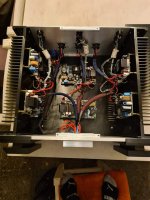
I might also try the 5v source othrrs were suggesting on the 50asx modules, but by 125asx modules are missing one of the wires needed, so I would need to see if I can buy individual wires with the pins on them.
Here is my 125asx 6 channel amp...I made it as clean as I could, but it is not as nice as the the single amp module one.
Here is my 125asx 6 channel amp...I made it as clean as I could, but it is not as nice as the the single amp module one.
Attachments
- Home
- Amplifiers
- Class D
- Convert 120v to 12v for LEDs